Table of Contents
Multivibrator
Multivibrator is a two-state device that finds its extensive application in digital electronics. These devices are constructed using resistor coupled amplifiers whose outputs are feedback. Multivibrators are used in the storage of binary numbers; to count clock pulses, to perform arithmetic operations but the main application being non-sinusoidal wave generation. It generates rectangular, square, sawtooth waves, etc.
Types of Multivibrator
Multivibrators are of different types:
- Bistable multivibrator
- Monostable multivibrator
- Astable multivibrator
Bistable Multivibrator
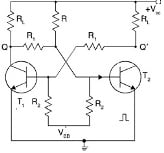
The bistable multivibrators are flip-flops that have two states. It exists in both states for any indefinite time. The state can be changed with external triggering. They are the basic memory devices used in sequential logic. They also function as pulse generator and pulse counter. The active devices in a bistable multivibrator are two n-p-n transistors. Though both the transistors are theoretically identical yet their practical characteristics show differences. This is because a minor difference in the base-emitter voltage of one transistor may cause it to conduct earlier than the other transistor. Secondly, the positive feedback of the second transistor T2 makes T1 to lag behind till it reaches saturation.
The voltages of the transistors T1 and T2 appear at outputs Q and Q’ respectively. Initially let us assume both the transistors to be in OFF state. Now T1 will be in saturation with zero collector voltage (VC1 = 0.2 V to 0.3 V). This is coupled to transistor T2 and since the voltage is nearly zero T2 is OFF. The collector voltage of T2 will be VCC = +5V. The outputs Q and Q’ are complementary to each other.
If Q is 1, then the output Q’ will be 0. The two outputs will remain in this state until the external pulse is applied. When Q is 1 and Q’ is 0 then flip-flop is in the SET condition. When Q is 0 and Q’ is 1 then flip-flop is in RESET condition. Generally, all flip-flops are given RESET before the start of the operations. By pressing RESET, a positive pulse is applied to T2 and the transistor goes to saturation state. This introduces an inversion action on Q that makes it 0.
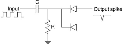
RC network used for ac pulse
The change of state is achieved by applying a trigger pulse. For triggering a dc pulse is preferred compared to ac since the hold time is more. This causes an increased holding action. Holding action refers to the process where the flip-flop is in ON state as long as the dc is present at the base. An ac pulse can be applied by passing it through a RC circuit coupled with diode as shown in figure below.
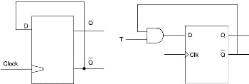
Truth Table & Circuit Diagram
Consider an ac pulse is connected to the base of the transistors T1. T1 is ON and T2 is OFF. Since the anode is maintained at +VCC, the diode conducts for a negative pulse and the base-emitter voltage of transistor T1 reduces below the cut-off voltage and hence turning it OFF. When another diode is connected to T2, it is called a pulse steering network. The introduction of an RC circuit along with a diode produces two output cycles one at T1 and T2. This is called as RS flip-flop. The circuit and the truth table are shown below.


In a bistable multivibrator, the two transistors are turned ON and OFF alternately. This causes a finite delay between ON and OFF operation. This delay or transition time is the time during which conduction transfers from one transistor to the other. This is caused by the stray capacitor CBE that induces an integration effect with the coupling resistors. To reduce the transition delay, the reverse bias voltage at the input capacitor of the transistor in OFF state must discharge before the base emitter voltage VBE becomes positive. The capacitors connected to increase the transition speed are called as commutating or speed up capacitors.
Monostable Multivibrator
Monostable multivibrators are cross coupled transistors having only one stable state. On applying a trigger pulse it transfers to quasi state. The transition time from the quasi state to the stable state depends on the time constant RC. Monostable multivibrators are also known as One-shot multivibrators as they are used to generate a single output pulse of a specified width on applying a suitable external trigger pulse.
During the stable condition, one of the transistors is ON and the other is OFF. The state can be changed by applying a negative pulse (logic 0) to the ON transistor or a positive pulse (logic 1) to the OFF transistor. The bi-stable multivibrator can be converted into a monostable multivibrator by replacing the coupling resistor of one transistor with a capacitor and by connecting the base of the same transistor to the main supply. The circuit of a monostable multivibrator shown below.
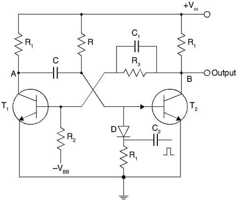
Waveform of monostable multivibrator
The collector of the second transistor is connected to the base of the first transistor through a parallel RC network formed by R3 and C1. And the collector of the first transistor is connected to the base of the second transistor through a capacitor C. When T2 is ON and T1 is OFF, the multivibrator is in a reset state.
From the circuit, it is seen that the transistor T2 is also connected to the main supply VCC through resistor R therefore, the base of transistor T2 is at 0.7 V and its collector is at 0.1 V. Transistor T1 is also maintained at VCC which charges the capacitor. When the trigger pulse is applied at terminal P, it reaches diode D through R2, C2 and produces a negative pulse to the base of the transistor T2 which pushes the transistor to the OFF state. The OFF state of transistor T2 produces its collector voltage to +VCC. The collector is connected to the base of transistor T1 causing a positive potential. This makes T1 ON.
Since T1 is connected to the base of T2 it goes to a low voltage thereby switching OFF T2. Thus, T1 is ON and T2 is OFF. This condition is known as the set state of the multivibrator. The state prolongs till the base of transistor T2 is increased. This is achieved by the capacitor that gets charged and increases the base voltage of transistor T2. Now T2 is driven to ON state and T1 goes to OFF state. The transition between the states continues for every trigger pulse applied. The waveform of the monostable multivibrator is shown in the figure below.
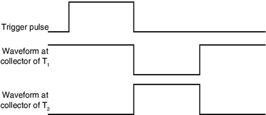
Monostable multivibrators are capable of producing both short pulse and longer rectangular shaped waveform. The leading edge of the waveforms rises with time of the externally applied trigger pulse while its trailing edge depends on RC time constant of the feedback components used. This RC time constant varies with time to produce a series of controlled time delay. The width of the pulse is calculated using the relation.
T = 0.693RC
Astable Multivibrator
An astable multivibrator has two cross coupled transistors with both quasi states. The transistors are coupled with each other through capacitors such that they form a feedback network. The capacitors does not allow any of the transistor permanently in ON state. This makes the astable multivibrators to switch continuously between the two unstable states at a constant repetition rate even in the absence of the external trigger pulse. Thus, an astable multivibrator is also known as free running oscillators that can produce continuous square waveform. These are capable of producing pulses when its square wave output is differentiated by passing it through RC network.

The circuit diagram shown in the above figure has two cross coupled transistors either NPN or PNP. The transistors are coupled through capacitors C1 and C2. Since the capacitors are used as feedback components, So the charge in the capacitors always keeps at least one of the transistors in the ON state. The charge on the capacitors completely controls the multivibrator and the voltage does not change instantaneously.
Waveform of astable
At a given instant of tine t = 0 let us consider transistor T1 be OFF and transistor T2 be ON state. The voltage at the collector of transistor T1 is +VCC and collector voltage of T2 is VCE. The base of T1 has negative potential and base voltage of transistor T2 is VBE. The capacitor C2 discharges and this in turn induces an increase in the base voltage of transistor T1. The voltage rises exponentially till it reaches VCC.
Once it reaches the cut off voltage Vγ, transistor T1 conducts. When T1 reaches the saturation, the voltage at the collector VC1 decreases to VCE, the saturation voltage. Now the charge on capacitor C1 does not change instantaneously and the fall in the collector voltage of T1 is applied to the base of T2. Thus, T2 sets to OFF state. The collector voltage of T2 increases till it reaches VCC that charges the capacitor C2. This capacitor is connected to the base of transistor T1. This in turn increases the collector voltage of T2. After the time period t = 0, the base voltage of T2 rises exponentially and reaches cut off voltage, Vγ. The process is repeated again reverse transition takes place. The waveform is depicted in the figure shown below.

The astable multivibrator is capable of switching between the two states even in the absence of trigger pulse. The time interval t1 and t2 are given as
- t1 = 0.693R1C1
- t2 = 0.693R2C2
Reference:
https://learning.oreilly.com/library/view/digital-electronics/9789332540828/xhtml/Ch09.xhtml
Related Post:
Multiplexer and implementation