Table of Contents
Resistor-Transistor Logic (RTL)
The resistor-transistor logic (RTL) are digital circuits that are constructed using resistors and bipolar junction transistors (BJTs). The resistors are the input network while the transistors function as switching devices. The disadvantage of Diode logic (DL) is overcome using RTL since the transistors not only operate as switches but also amplify signals.
RTL family was the first developed transistor logic circuits that were later improved to form the other classes like diode–transistor logic (DTL) and transistor-transistor logic (TTL). The introduction of the RTL family revolutionized circuit technology by constructing the first monolithic integrated circuit.
Resistor-Transistor Logic (RTL) NOT Gate
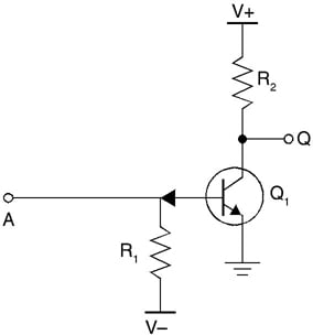
A RTL inverter or NOT gate is shown in figure below.

Bipolar transistor switch is the simplest RTL gate. The resistor R1 in the circuit is used across the base and input terminals. This resistor increases the voltage drop from 0.7 V to 1 V by converting the input voltage into current. The resistance R1 is chosen in such a way that it saturates the transistor and obtains high input resistance. The collector resistor R2 converts collector current into voltage. The resistance of R2 is high to saturate the transistor and low to obtain output resistance.
RTL NOR Gate
The RTL NOT gate can be converted into an RTL NOR gate by introducing additional base resistors R3 and R4. The circuit of an RTL NOR gate is shown in the figure below.
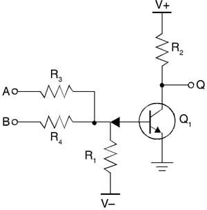
When both A and B are given logic 0, then the transistor is cut-off. The output is inverted since it is complimentary. This is because the voltage drop across the collector-emitter junction of the transistor Q1 is taken at Q instead of taking it across collector resistor R2.
Multistage NOR Gate
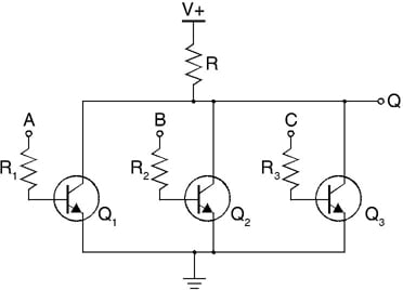
A multistage NOR gate circuit is shown in the figure below. It consists of parallel connections of BJTs that are controlled by input logic. The inputs are not interconnected and hence if A is high, transistor Q1 conducts and pulls Q to the ground. Similarly, if B is high then transistor Q2 conducts and pulls Q to the ground.
Advantages and Limitations of RTL
Minimum transistors are required to implement logic expressions. RTL leads to the much-improved logic families like diode–transistor logic and then transistor-transistor logic.
The disadvantage is that the RTL has high power dissipation especially when the transistor is at logic 1.
Related Post: