Table of Contents
Compensator
The compensator circuits basically introduce a pole and/or zero to the existing system to meet the desired specifications. The compensators may be designed using electrical, mechanical, pneumatic or any other components. The basic idea of determining the transfer function of the compensator is to suitably place the dominant closed-loop poles of a system. Compensated systems can be classified into six categories based on the location of compensators in the system as follows:
- Series or cascade compensation
- Feedback or parallel compensation
- Load or series-parallel compensation
- State feedback compensation
- Forward compensation with series compensation
- Feed-forward compensation
Series or Cascade Compensation
In this type of compensated system, the compensator is included in the feed-forward path of the system as shown in the figure below.

The addition of compensator in the feed-forward path adjusts the gain of a system which reduces the response time and peak overshoot of the system. In addition, the stability of the system gets reduced.
Feedback or Parallel Compensation
In this type of compensated system, the compensator is included in the feedback path of a system as shown in figure below.

The addition of compensator in the feedback path increases the response time of the system that makes it accurate and more stable.
Load or Series-Parallel Compensation
The combination of both series and parallel compensation shown in the figure below is known as load or series – parallel compensation.

State Feedback Compensation
In this type of compensation, the control signal in the form of a state variable is fed back as a control signal through the constant real gain as shown in the figure below.
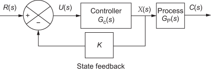
The implementation of the state feedback compensation is costly and impractical for higher order systems.
11.2.5 Forward Compensation with Series Compensation
When a simple closed-loop system is in series with the feed-forward controller, Gcf(S), the resultant compensation is the forward compensation with series compensation that is shown in the figure below.

Feed-forward Compensation
When the feed-forward controller Gcf(S), is placed in parallel with the forward path of a simple closed-loop system, the resultant compensation is the feed-forward compensation that is shown in the figure below.

The compensated systems are shown in Series or cascade compensation, Feedback or parallel compensation, and State feedback compensation have one degree of freedom which intimates that the system has a single controller. The disadvantage of one degree of freedom controller is that the performance criteria realized using these compensation techniques are limited.
In simple words, the compensators introduce additional poles/zeros to an existing system so that the desired specification is achieved.
Effects of Addition of Poles
The following are the effects of addition of poles to an existing system:
- The root locus of a compensated system will be shifted towards the right-hand side of the s-plane.
- Stability of a system gets lowered.
- Settling time of a system increases.
- Accuracy of a system is improved by the reduction of steady-state error.
Effects of Addition of Zeros
The following are the effects of addition of zeros to an existing system:
- The root locus of a compensated system will be shifted towards the left-hand side of the s-plane.
- Stability of a system gets increased.
- Settling time of a system decreases.
- Accuracy of a system is lowered as steady-state error of the system increases.
Choice of Compensators
The choice of compensators from the different categories discussed in the previous sections is based on the following factors:
- Nature of signal to the system
- Available components
- Experience of the designer
- Cost
- Power levels at different points and so on
Related Posts: