Table of Contents
Stepper Motor
A special type of synchronous motor designed to rotate through a specific angle for each electrical pulse applied is known as a stepper motor. The specific angle through which the stepper motor rotates is called step. Electrical pulses are received from the control unit of the stepper motor. It is used along with electronic switching devices whose function is to switch the control windings of the stepper motor according to the command received.
The stepper motor has gained importance in recent years because of the ease with which it can be interfaced with digital circuits. It completes a full rotation by sequencing through a series of discrete rotational steps (stepwise rotation). Each step position is an equilibrium position so that without further excitation the rotor position stays at the latest step. Thus, continuous rotation is achieved by a train of input pulses, each of which causes an advance of one step. It can be variable reluctance, permanent magnet, or hybrid depending on the type of rotor. It can also be classified into two-phase, three-phase, or four-phase depending on the number of windings on the stator.
Permanent Magnet Stepper Motor
In this type, the stator has salient poles that carry control windings. A phase is created when the two control windings are connected in series. The rotor of this type of stepper motor is made in the form of a spider cast integral permanent magnet or assembled permanent magnets. The schematic diagram showing the different types of rotor structure is shown in the figure below.

The permanent magnet stepper motor operates at a larger steps upto 90° at a maximum response rate of 300 pps.
Variable Reluctance Stepper Motor
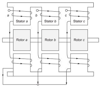
In this type, it has a single or several stacks of stator and rotor. The stator has a common frame, whereas the rotor has a common shaft. In this type, the stator and rotor have a toothed structure. The longitudinal cross-sectional view of the three-stack variable reluctance stepper motor is shown in the figure below.
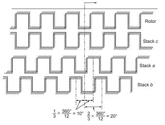
The difference in angular displacement of stator and rotor when the teeth of the rotors are perfectly aligned is given by
\alpha =\frac{360^{0}}{nT}where n is the number of stacks and T is the number of rotor teeth.
The schematic diagram explaining the concept of the separation between the stator and rotor is shown in figure below.
Hybrid Stepper Motor
This is similar to the permanent magnet type with the constructional features rotor adopted from the variable reluctance stepper motor. The polarities of the teeth on the stack of the rotor at both ends are of different polarities. Thus, the two sets of teeth in the rotor are displaced from each other by one-half of the tooth pitch (pole pitch). The constructional features of this type are shown in the figure below.

Operation of Stepper Motor
Depending on the step angle by which it’s rotates, the operation can be classified as
- full-step operation
- half-step operation
- micro-step operation
Full-Step Operation: In this type of operation, the motor moves one full step for each of the input pulses applied.
Full step =\frac{360^{0}}{N_{R}\ast N_{S}}
where NR is the number of rotor poles and NS the number of stator pole pairs.
Half Step Operation: In this type of operation, the motor moves one-half of the full step for each of the input pulse applied. If in the full-step operation of the stepper motor, for each input pulse it rotates at X0, then in the half-step operation of the motor, it will rotate at X0/2 for each input pulse.
Micro Step Operation: In this type of operation, the motor moves through an angle of 1/10, 1/16, 1/32, and 1/125 of a full step. The major advantage of this type of operation is that it provides much finer resolution.
Advantages
- It is compatible with digital systems.
- No sensors are required to sense the speed and position.
- Motors are available in larger power ratings with reduced cost.
- Motors are available with the torque range of 0.5 micro N-m to 100 N-m.
- It is used to upgrade mechanical systems to give greater precision and production rate.
Applications
- It is used in computer peripherals (printers, disk drives, etc.), X–Y plotters, scientific instruments, and machine tools.
- It is used in quartz crystal watches.
- Many supporting roles in the manufacture of packaged foodstuffs, commercial end products, and even in the production of science fiction movies.
Related Post: