Table of Contents
Telemetry, Tracking and Command (TT&C) Subsystem
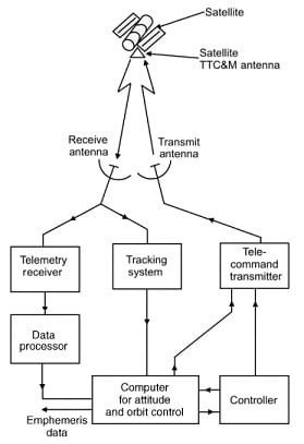
The tracking, telemetry, and command (TT&C) subsystem monitor and controls the satellite right from the lift-off stage to the end of its operational life in space. The tracking part of the subsystem determines the position of the spacecraft and follows its travel using angle, range, and velocity information. The telemetry part gathers information on the health of various subsystems of the satellite. It encodes this information and then transmits the same towards the Earth control center. The command element receives and executes remote control commands from the control center on Earth to effect changes to the platform functions, configuration, position, and velocity.
The TT&C subsystem is therefore very important, not only during orbital injection and the positioning phase but also throughout the operational life of the satellite.
Data received from the satellite about status of attitude, orbit and other parameters, is processed at the ground station. Telemetry, tracking and command subsystem is a part of satellite management task and it involves an earth station. The main functions of the TT&C subsystems are:
- Measurement of angle and range for the localization of the satellite.
- Transmission of housekeeping information.
- Status of satellite to the ground control station.
- Receiving command signals for station keeping operations of theco:nrdd equipments.

Telemetry
Telemetry system collects the the data from many sensors and sends this data to the controlling earth station. The sensors are mounted on the satellite and they monitor:
- The pressure in fuel tank.
- Voltage and currents in the power conditioning unit.
- Current drawn by each subsystem.
- Critical voltage and currents in the communication electronics.
- Temperature of other subsystems.
- Position of switches and attitude.
Typically 100 sensors are required to monitor these data When the satellite is in transfer orbit, the telemeter transmitter is connected to a TWTA in the satellite repeater. The telemetry data is digitized in nature and transmitted as frequency or phase shift keying (FSK or PSK) of a low power telemetry carrier using time division techniques.
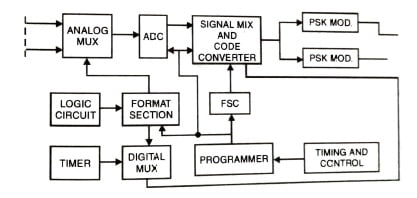
To maintain a high carrier to noise ratio and narrow bandwidth, a low data rate is used to allow the receiver at the earth station. The entire TDM frame can take several seconds to transmits thousands of bits of data. The controlling earth station uses a computer to monitor, store and decode the telemetry data so that the status of any system or sensor on the spacecraft can be determined. Alarms can also be used if any parameter goes outside the allowable limits.
Tracking or Ranging
It determines the slant range for accurate determination of satellite orbit. It can be done in two ways:
- By transmitting a command carrier modulated by multiple tones from the earth station to the satellite. The carrier is received by the command receiver in the satellite, demodulated and then goes to the teletnetry or beacon transmitter for retransmission to the earth, where the phase difference of the received signal is measured with respect to the transmitted signal.
- Velocity and acceleration sensors can be used in the satellite to sense the change in the orbit. This data can be sent to the earth station through telemetry, where commands are generated and sent to the satellite for orbit correction.
Command Subsystem
For common operation the satellite contains a receiver which works only for command signal transmitted from the TTC earth station. By this command subsystem controls the satellite operation by receiving and decoding command from the TTC earth station. The communication antenna is used for command and ranging when the satellite is in synchronous orbit and, during the satellites position in transfer orbit the omnidirectional antenna is used for command and ranging.
During the injection of satellite into geostationary orbit a back up system is used which provides:
- The control of apogee boost motors.
- Attitude control systems.
- Orbit control thrusters.
This back up system works with omnidirectional antenna at either UHF or S-band (2-4 GHz) and sufficient margin is required in the signal to noise ratio (S/N) at the satellite receiver. In case of failure of main TT&C system. the back up system canbe used to keep the satellite on station. It is also used to enject the spacecraft from geostatiortary orbit and to switch off all transmitters, when it reaches the end of its useful life.

- Decoder reproduce command messages and produce lock/enable and clock signals.
- Command logic validates the command.
- Default is to reject if any uncertainty of validity.
- Drives appropriate interface circuitry.
- Command decoder detect PCM encoding and outputs binary stream in non-return to zero format. It activates downstream command subsystem components.
- The function of Interface circuitry are latching relays with teletales, pulse commands, level commands and, serial and parallel data commands.
Telemetry, Tracking, and Command Subsystem Interface
The different subsystems and their requirements are listed in Table below:
| S. No. | Subsystem | Requirements |
| 1. | Attitude determination and control | Antenna pointing |
| 2. | Command and data handling | 1. Command telemetry data rates 2. Clock, bit sync, timing requirements 3. Two-way communication requirements 4. Autonomous fault detection and recovery 5. Command and telemetry electrical interface |
| 3. | Electrical power subsystems | Distribution requirements |
| 4. | Thermal/ Structural | 1. Heat sinks for TWTAs 2. Heat dissipation for all active boxes 3. Location of TT&C subsystem 4. Ceal field of view and movements for all antennas |
| 5. | Payload | 1. Storing mission data 2. RF interface requirements 3. Special requirements for modulation and coding |
Related Posts:
