Table of Contents
Thermocouple
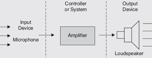
A thermocouple consists of a pair of dissimilar conductors welded or fused together at one end to form the hot or measuring junction with other ends available for connection to the cold or reference junction. A thermocouple is a thermoelectric device that converts thermal energy into electrical energy. The thermocouple is used as a primary transducer for measurement of temperature, converting temperature changes directly into emf.

There are two types of effects that arise when two dissimilar metals are brought in contact with each other and the temperature is changed at the junction. One effect produces an electrical potential (Seeback effect) when heat is applied and the other effect is to cool the junction when a current is passed through the junction in the proper direction (Peltier effect). These two effects can be very useful. Since the voltage at the junction depends upon the temperature of the end points, we may generate a voltage by heating one junction while holding the other constant in temperature. This effect make a cooling device, a refrigerator, by passing a current through the junction in the proper direction.
There are two junctions T1 and T2. The junction T2 is kept at the constant reference temperature and referred to as a cold junction while the junction T1 is referred to as a hot junction. When the hot junction temperature is greater as compared to the cold junction an emf is generated due to the temperature gradient. The magnitude of the emf depends on the material used for the wires and the temperature difference between the two junctions. A meter or recorder is used to measures emf as shown in the figure below.

Types of Thermocouple
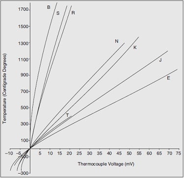
There are several types of thermocouples are available, and different types are designated by capital letters that indicate their composition according to American National Standards Institute (ANSI) conventions. For example, a J-Type thermocouple has one iron conductor and one constantan (a copper-nickel alloy) conductor. The list of thermocouples is given in the table below.
Table | Types of Thermocouple
| Thermocouple Type | Conductors – Positive | Conductors – Negative |
| B | Platinum-30% rhodium | Platinum-6% rhodium |
| E | Nickel-chromium alloy | Copper-nickel allo |
| J | Iron | Copper-nickel alloy |
| K | Nickel-chromium alloy | Nickel-aluminum alloy |
| N | Nickel-chromium-silicon alloy | Nickel-silicon-magnesium alloy |
| R | Platinum-13% rhodium | Platinum |
| S | Platinum-10% rhodium | Platinum |
| T | Copper | Copper-nickel alloy |
The figure is shown below the thermal EMFs for some common thermocouple materials. The values are based on a reference temperature of 32°F.
Measurement of Temperature with Thermocouple
T Type Thermocouple
In the figure shown below a T-type thermocouple uses copper and constantan. Copper used is an element and constantan use is an alloy of nickel and copper. The copper side is positive and the constant side is negative. Assuming copper wires used to connect the thermocouple to the next stage and second copper-constantan junction is produced. The junction is called a reference junction. It generates a seeback voltage that opposes the voltage generated by the sensing junction.
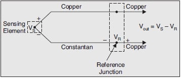
When the both junction are at the sane temperature the output voltage is zero. If the sensing junction is at high temperature the output voltage is proportional to the difference between the two junction temperatures.
With Cold Junction Compensation
The temperature cannot be delivered directly from the output voltage, it may cause an error produced by the reference junction. This error is overcome by placing the reference junction in the ice bath of a known temperature as shown in the figure below.

This process is called as cold junction compensation. The reference voltage is maintained at 0°C. The reference voltage is now predictable from the calibration curve of the T type thermocouple.
For accurate measurement of hot junction temperature the cold junction or reference junction must kept at 0°C. If the cold junction is at ambient temperature then a voltage corresponding to this temperature must be added to the measurement to obtain accurate reading.
J Type Thermocouple Using Isothermal Block
When copper is not one of the thermocouple metals then the four junction circuit is formed as shown in the figure below. This is J-type thermocouple uses iron and constantan as the two elements, When it is connected to copper wires, two iron copper junctions, reference junctions, and sensing junctions are formed. Here we used an isothermal block. This block is made of materials that have a poor conductor of electricity but a good conductor of heat. Both iron-copper junctions will be at the same temperature and generate the same seeback voltage and hence these two voltages will cancel. In industry, it is not possible to use the ice-baths method so we use a different method for cold junction compensation.
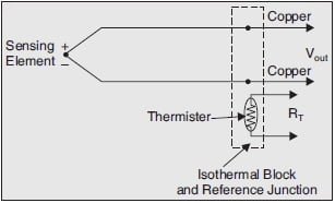
The isothermal block contains two reference junctions and a thermistor. The resistance of the thermistor is a function of temperature. The circuit is used to sense the resistance of the thermistor and to compensate for the voltage introduced by the two reference junctions. An isothermal block with one temperature sensor can provide compensation for several units.
Types of Junction in Thermocouples
When thermocouples are assembled into metal-sheathed thermocouples, there are the following ways to assemble the thermocouple junction.
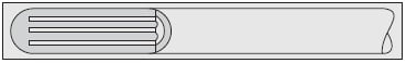
Grounded Junction
The figure shown below the grounded junction when assembling the thermocouple into a protective metal sheath, the thermocouples junction is weld directly to the inside tip of the sheath. Grounded thermocouples temperature sensors are widely used because they offer faster response time, more accurate reading at short distances. It is a preferred junction type for high-temperature applications. Precaution for a ground loop at long distances and at low-temperature usage.
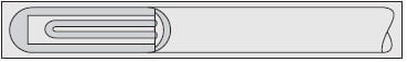
Ungrounded Junction
The figure is shown below the ungrounded junction this is similar to the grounded junction except it is isolated from the metal sheath. Ungrounded thermocouples are used primarily for isolating the control system from the sensor and to prevent ground loops. It is more inaccurate and slow response time.
Exposed Junction
The figure is shown below the exposed junction. The junction is directly exposed to the material being heated, the junction response is very quickly to temperature changes. There is no sheath or insulation to slow down heat transfer.
Materials for Thermocouple
Some of the property of material used for thermocouple are given below:
- The melting point of thermocouple materials must be higher than the measuring temperature.
- The dissimilar materials on joining should be able to produce large emf for accuracy of measurements.
- Temperature is determined indirectly i.e. through calibrations of emf with temperature. As for as possible, the linear variation of emf with temperature is desired.
- Thermocouple materials should be resistant to atmospheres in furnaces.
Advantages of Thermocouple
Some of the advantages of thermocouples are given below:
- The thermocouple junction may be grounded and brought into direct contact with the material being measured.
- The thermocouples are rugged in construction
- It covers a wide range of temperatures from –270° C to 2700° C.
- Using extension leads and compensating cables, long distances transmission for temperature measurement is possible.
Disadvantages of Thermocouple
Some of the main disadvantages of thermocouple are given below:
- Temperature measurement with a thermocouple requires two temperatures to be measured, the junction at the working end (the hot junction) and the junction where wires meet the instrumentation copper wires (cold junction).
- Thermocouples operations are relatively complex with potential sources of error.
- They have lower accuracy and hence they cannot be used for precision work.