Table of Contents
Zener Vs Avalanche Breakdown
Break Down Mechanisms
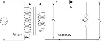
Zener Vs Avalanche Breakdown: When an ordinary P-N junction diode is reverse biased, normally only very small reverse saturation current flows. This current is due to the movement of minority carriers. It is almost independent of the voltage applied. However, if the reverse bias is increased, a point is reached when the junction breaks down and the reverse current increases abruptly. This current could be large enough to destroy the junction.
If the reverse current is limited by means of a suitable series resistor, the power dissipation at the junction will not be excessive, and the device may be operated continuously in its breakdown region to its normal (reverse saturation) level. It is found that for a suitably designed diode, the breakdown voltage is very stable over a wide range of reverse currents. This quality gives the breakdown diode many useful applications as a voltage reference source.
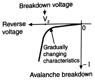
The critical value of the voltage, at which the breakdown of a P-N junction diode occurs, is called the breakdown voltage. The breakdown voltage depends on the width of the depletion region, which, in turn, depends on the doping level. The junction offers almost zero resistance at the breakdown point.
There are two mechanisms by which breakdown can occur at a reverse-biased P-N junction:
- Avalanche breakdown
- Zener breakdown
Avalanche Breakdown
Consider a reverse-biased diode. A thermally generated carrier (forming part of the reverse saturation current (Is) falls down the junction barrier voltage since electrons on p-side arid holes on n-side (which form the minority carriers in their respective region) are assisted by a reverse bias. In fact, the depletion region barrier voltage V0 assists the minority carriers along with the externally applied reverse bias, to fall towards the junction. If the value of V0 plus the reverse bias (applied externally) is sufficiently high then the thermally generated carriers acquire energy and gain velocity from the applied reverse voltage.
These sufficiently high-velocity carriers collide with a crystal ion, impart this ion sufficient energy and consequently disrupt its covalent bond. In addition to the original carriers (which disrupted the covalent bond), a new electron-hole pair is also generated. This additionally generated carrier may also pick up sufficient energy and generate still other electron-hole pairs by collision by disrupting other covalent bonds. This process results in a large reverse current and the diode is said to have avalanche breakdown.
Zener Breakdown
Here, the breakdown of the covalent bonds takes place not by collision (as in avalanche breakdown) but by producing a sufficiently high electric field at the junction. A sufficient strong force may be exerted on the covalently bound electrons such that the strong field tears off the covalent bonds. In the tearing process, we have generated an electron-hole pair. These newly created electron-hole pairs increase the reverse current. Note that the Zener breakdown does not involve a collision of carriers with the crystal ions.
Zener breakdown occurs at about the field intensity of 2 x 10⁷ V/m. This value is achievable by a reverse voltage of 6 V using heavily doped junctions. For lightly doped diodes, the breakdown voltage is higher, and there the avalanche multiplication is predominant.
Silicon diodes operated in avalanche breakdown for maintaining voltages from a few volts to several hundred volts and with power ratings up to 50 W are available.
Though the end results of both the avalanche breakdown and the Zener breakdown are the same (generation of very high currents) there are few vital differences in these processes, as follows:
Comparison between Zener Breakdown and Avalanche Breakdown
| S.No. | Zener Breakdown | Avalanche Breakdown |
| 1 | Caused by field ionization. | Caused by impact ionization. |
| 2 | Direct bond rupture occurs due to a high electric field at the junction. | Due to high fields, the charge carriers acquire high velocities, i.e. high energies sufficient to ionize the electron-hole pairs. The carriers, thus liberated, ionize further electron-hole pairs. It is a cumulative effect. |
| 3 | Zener effect occurs at approximately 2 x 10⁷ V/m. This value is reached at voltages below about 6 V. | Avalanche effect occurs at voltages usually above 7 V. |
| 4 | Zener diodes have lower resistance. | Avalanche diodes have higher resistance. |
| 5 | Zener diodes are heavily doped. | Avalanche diodes are not heavily doped. |
| 6 | The breakdown voltage decreases with an increase in temperature. | The breakdown voltage increases with an increase in temperature. |
| 7 | For reference voltage below 6 V (and hence Zener breakdown), the temperature coefficient is negative. | For reference voltage above 6 V, (and hence Avalanche breakdown), the temperature coefficient is positive. |
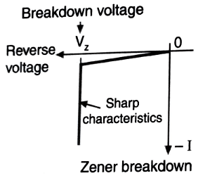
| 8 | V-I characteristics with the Zener breakdown are very sharp. | V-I characteristics with avalanche breakdown increase gradually. It is not as sharp as that with the Zener breakdown. |