Table of Contents
Wave Analyzer
A wave analyzer is an instrument designed to measure the relative amplitude of signal-frequency components in a complex or distorted waveform. The analysis is in the frequency domain and can be done with a set of tuned filters and a voltmeter.
Wave analyzer is also called frequency-selective voltmeters, carrier frequency voltmeters or selective level voltmeters. The instrument is tuned to the frequency of the component whose amplitude is to be measured.
Wave analyzers are used in the low RF range, below 50 MHz and down through the AF range. The wave analyzer provides a very high-frequency resolution.
Types of wave analyzer:
- Basic Wave analyzer
- Based upon the frequency ranges
- Frequency selective wave analyzer (frequency ranges from 20 Hz to 20 kHz)
- Heterodyne wave analyzer (frequency ranges from 10 kHz to 18 MHz)
Basic Wave Analyzer
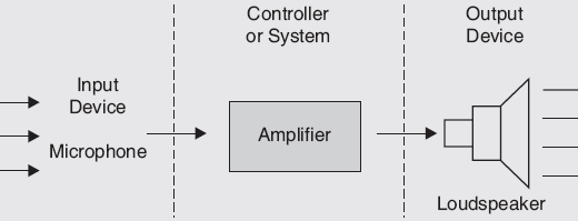
A wave analyzer is an instrument designed for measuring the relative amplitudes of single frequency components in a complex or distorted waveform. Basically the instrument acts as a frequency-selective voltmeter which is tuned to the frequency of one signal component while rejecting all the other signal components. The amplitude is indicated either by a suitable voltmeter or a CRO. The basic wave analyzer is shown below.

It consists of:
(a) Primary Detector: This is a simple LC circuit. It’s adjusted for resonance at the frequency of the particular harmonic component to be measured.
(b) Full-wave rectifier: It is an intermediate stage of the basic wave analyzer. It obtains the average value of the input signal.
(c) Indicating Device: The indicating device is a simple dc voltmeter that is calibrated to read the peak value of the sinusoidal input voltage. The LC circuit is tuned to a single frequency of the input signal and rejects all other frequencies. The full-wave rectifier provides the average value of the input. A number of tuned filters are connected to the indicating device thorough a selector switch.
Principle:
- It operates on the principle of a frequency selective voltmeter. It is tuned to the frequency of one signal and rejects all other signal components.
- The desired frequency is selected by a frequency calibrated dial to point maximum amplitude. The amplitude is indicated by a suitable voltmeter or a CRO.
- It consists of a primary detector made of an LC circuit. The LC circuit is adjusted for resonance at the frequency of the particular harmonic component to be measured.
- The intermediate stage is a full-wave rectifier. It is used to obtain the average value of the input signal, on the indicating meter. The indicating meter is a DC voltmeter calibrated to read the peak value of the input voltage.
Frequency Selective Wave Analyser
The frequency selective wave analyzer is used for measurements in the audio frequency ranges from 20 Hz to 20 kHz. The block diagram of the frequency selective analyzer is shown below. It consists of a narrow pass-band filter section that can be tuned to a particular frequency. The block diagram consists of an attenuator, drive amplifier, High Q active filter, meter circuit, and buffer amplifier.
Principle:
- The frequency selective wave analyzer operates on the principle of the frequency-selective voltmeter. It is tuned to the frequency of one signal and rejects all other signal components.
- It is used for measurement in the audio frequency range from 20 Hz to 20 kHz.
- The analyzer has a filter section with a very narrow passband, so that frequency can be tuned.

Working:
- The waveform which is to be analyzed is applied to an input attenuator. It acts as a range multiplier and allows a large range of signal amplitudes to be analyzed without loading the amplifier.
- The driver amplifier feeds the waveform to a high Q active filter.
- The filter consists of a cascaded arrangement of RC resonant sections and filter amplifiers. The entire AF range is covered in decade steps by the switching capacitors in the RC sections.
- Close tolerance polystyrene capacitors are used for selecting the frequency ranges.
- Precision potentiometers are used to tune the filter to any desired frequency within the selected passband.
- The final amplifier supplies the selected signal to the meter circuit and to an unturned buffer amplifier.
- The buffer amplifier is used to drive the output of devices like recorders, electronics counters, etc.
- The meter is driven by an average type detector and has several voltage ranges as well as the decibel scale.
- The instrument should have low input distortion.
- The bandwidth of the instrument is very small, typically 1% of the selected frequency.
Heterodyne Wave Analyser
The ordinary wave analyzer is useful for measurement in audio frequency range but not for radio frequency (RF) range and above (MHz) ranges. To measure the frequency in the MHz range, special types of wave analyzers operating on the principle of heterodyning (mixing) are needed. Such wave analyzers are called the heterodyne wave analyzers.
Principle:
- It works on the principle of heterodyning or mixing. The input signal to be analyzed is heterodyned i.e. mixing to a higher intermediate frequency (IF) by an internal local oscillator.
- The signal frequency components shift into the passband of the IF amplifier because of the tuning of the local oscillator.
- The output of the IF amplifier is rectified and applied to the metering circuit.

Working of Wave Analyzer:
- The operating range of this device is from 10 kHz to 18 MHz in 18 overlapping bands, which can be selected by the frequency range control of the local oscillator.
- The bandwidth is controlled by an active filter. It can be selected at 200, 1000 and 3000Hz.
- The input signal is applied to the input attenuator, through a probe connector that contains a unity gain isolation amplifier. The output is in the range of 0-18MHz.
- The unturned amplifies the signal and gives it to the mixer.
- The first mixer heterodynes this signal with frequency from the local oscillator. This oscillator has a frequency range from 30-48 MHz. The output of the first mixer is 30MHz.
- The IF amplifiers this before giving it to the second mixer.
- The second mixer mixes the amplified signal with a 30 MHz from the crystal oscillator.
- The output frequency is zero.
- This information cantered on zero frequency is given to an active filter.
- The active filter has controlled bandwidth and symmetrical slopes of 72dB per octave.
- The active filter passes the selected component can be read a decibel calibrated scale or may be applied to a recording device.
Applications of Wave Analyser
Following are some of the important applications of Wave Analyser, which are important from the subject point of view:
- It is used to measure the harmonic distortion of an amplifier. Each individual component of a periodic signal can be determined.
- It can be used to separate and display about harmonics.
- Measure relative amplitudes of signal frequency components in a complete waveform.
- Measure the signal energy with well-defined bandwidth.
- The wave analyzers are applied industrially in the field of reduction of sound and vibrations generated by rotating electrical machines and apparatus.
- Measure the amplitude in the presence of noise and other interfering signals.
- Use in harmonic analysis.
You may also like to read Spectrum Analyzer.