Table of Contents
MTI Radar
MTI radar stands to Moving Target Indicator radar.
MTI radars: The MTI radar’s main objective is to reject the signals from stationary unwanted signals i.e., ground clutter, rain clutter, bird clutter, etc., that arrive as an echo along with the desired echo of the signal. In MTI, the processing system is used to eliminate unwanted clutter from the background and to detect moving targets even when the velocity of such targets is small relative to the radar platform. There are two basic types of MTI radars, namely,
- Coherent MTI
- Non-coherent MTI
In coherent systems the receiver preserves the transmitted wave’s phase in order to detect the Doppler shift in frequency. In coherent MTI systems, the Doppler shift in the echo signal from the moving target is used to differentiate it from stationary target. But in non-coherent MTI systems, the moving targets can be detected by observing the relative motion between the target and clutter background, and also by observing corresponding changes in amplitudes of pulses. Coherent detection requires dealing with the envelope of a signal, g (t) and the phase of the sinusoidal carrier, Φ (t). They need not be measured directly, but can be derived using inphase (I ) and quadrature (Q) channels.
Types of MTI Radars
There are two basic types of MTI radars, namely coherent and non-coherent MTI. The coherent MTI radar differentiates moving targets from stationary targets by using the Doppler shift passed on to the reflected signal by a moving target. The non-coherent radar detects the moving targets by the relative motion between the target and the clutter background and, thus by the corresponding amplitude changes from pulse to pulse or from one antenna scan to the next. In Coherent systems, the phase of the transmitted wave should be saved so that it is used by the receiver to detect Doppler shift in frequency, but it is not required in non-coherent systems.
The composite echo signal fluctuates in both phase and amplitude when it is reflected from a moving target and clutter. The Doppler component of moving target can be identified by the coherent Pulse Doppler radar and MTI radar using the fluctuations in phase of the signal. The MTI radars are categorized into two types.
- Non-coherent MTI radars
- Coherent MTI radars
Non-Coherent MTI Radars
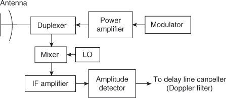
A non-coherent radar is defined as an MTI radar which uses amplitude fluctuations instead of phase fluctuations. An internal coherent reference signal or a phase detector is not needed by non-coherent MTI radar. The IF amplifier used in this radar should be linear and should have large dynamic range. It can be logarithmic so that logarithmic-gain characteristic provides protection from saturations. Amplitude detector is used after the IF amplifier and this detector is a conventional detector. The local oscillator need not be very stable. The figure shown below shows the block diagram of noncoherent radars.

The major advantage of a non-coherent MTI is that it is simple and it is mostly used in applications where space and weight are limited. The improvement factor of the non-coherent MTI, is not good. Clutter itself is the reference signal in the non-coherent radar. It will not detect moving targets, if clutter is not present.
Coherent MTI Radars
Coherent MTI radars can be of two types:
- MTI radar using a power amplifier as a transmitter
- MTI radar using a magnetron oscillator in place of an amplifier
MTI radars (Using power amplifier as transmitter)
A simple block diagram of an MTI radar is shown in figure below. The power amplifier is used as the transmitter in this type of MTI radar. Two local oscillators provide reference signals to the mixer. The coherent reference is provided by an oscillator called Coho, meaning coherent oscillator which is a stable oscillator. It has the same frequency of the IF used in the receiver. The output of the Coho fc is also mixed with the stable local oscillator frequency, besides providing reference signals. The other local oscillator should be a stable oscillator and is called a stable local oscillator (STALO).
For MTI radar, the local oscillator’s stability of superhetrodyne receiver must be more than the stability of local oscillator of radar which is not having Doppler. There may be a possibility of appearing uncancelled clutter residue at output of delay line canceller. This may lead to wrong detection of moving target although only clutter is present.

Instead of an amplitude detector as in the non-coherent radar, there exists a phase detector after the IF stage. This act is similar to a mixer in which the received signal coming from IF and the reference signal from the Coho is mixed to produce the difference between their frequencies. This difference is the Doppler frequency. The input signal applied to the power amplifier is nothing but the sum of Coho fc and Stalo signals fl. This is accomplished in the mixer as shown in above figure.
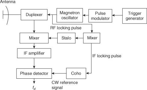
MTI radars using a magnetron oscillator in place of an amplifier
The block diagram of MTI radar is shown in figure below. In this magnetron oscillator acts as a transmitter. The phase of IF beat signal depends on the phase of Coho. This IF beat signal is produced by mixing transmitted signal and Stalo output. The phases of Coho and transmitted pulse are interrelated. The Coho signal can be used as the reference signal for echoes of a particular transmitted pulse. The COHO lock pulse is produced by the transmitted pulse. To again relock the phase of CW Coho another IF locking pulse is generated and continues upto next locking pulse. The block diagram of MTI radar with power oscillator transmitter is shown in Figure.
The two methods described earlier are not the only ones that are used for obtaining coherent reference signals in the MTI. The various arrangements may be classified accordingly: whether
- The transmitter locus the oscillator or vice versa
- The locking takes place at RF or IF
- The echo and the reference signals are accomplished at RF or IF. This results in eight possible combinations.
Advantages of MTI radars
- Elimination of clutter signals.
- Detection of smaller moving targets in the presence of clutter echoes.
- Minimizes the noise effect
- Useful range can be increased for a given power.
Disadvantages of MTI radars
- Low sub-clutter visibility
- High equipment instabilities cause lower improvement factor of MTI radars.
- The MTI radar can be limited by internal fluctuations of clutter (clutter from trees, rain, chaff, and sea).
- Due to limiter in MTI radars, performance may be degraded.
Applications of MTI radars
- Space-borne applications
- Unmanned aerial vehicles
- Some applications relative to ground MTI are locating, tracking, classifying, and identifying moving vehicles.
- Maritime moving target indicators (MMTIs)