Table of Contents
Duplexer
A duplexer is an electronic switch that facilitates a single antenna to be used for both transmission and reception. But the problem arises when an antenna is switched between the transmitting and receiving modes; that is the switching system has to ensure that the maximum use is made of the available energy. To overcome the problem, a switch is to be used to change the receiver connected to the transmitter during the transmitted pulse and to the receiver during the echo pulse. In this scenario, a mechanical switch cannot be used practically, as the switching operation is to be done in a few microseconds. So, electronic switches must be used.
Types of Duplexer
There are different types of duplexer have been used, a brief explanation of these duplexers are given below:
- Balanced Duplexer
- Branch Duplexer
- Ferrite Duplexer
Balanced Duplexer
The balanced duplexer can work at higher frequencies by having higher bandwidth. A balanced duplexer contains two sections of waveguides. They are joined along one of their narrow walls having a slot cut in the common wall. This provides coupling between the two waveguide sections. This is based on the short-slot hybrid junction. In each section of the waveguide, one TR tube is used. In the transmit condition, the power is evenly divided into each waveguide by the first hybrid junction which is on the left. The incident power is reflected out of antenna when both TR tubes break down as shown in figure below. The short-slot hybrid junction possesses a property that its phase is increased by 90° every time the power passes through the slot in any of the directions; the power traveled is indicated by the solid lines. In case of any power leaks through the TR tubes (indicated by the dotted lines), then it is directed to the arm and matched with the dummy load but not to the receiver. Isolation of 20 to 30 dB is provided by the hybrid junctions along with the attenuation offered by the TR tubes.

During the receive period, the signal enters the receiver through the duplexer. In this case, the TR tubes do not fire as shown above figure. The received power through the antenna will be divided equally at the first junction and they recombine in the receiver arm as they are in the same phase. Due to 180° phase difference between the signals entering into the dummy load arm, no signal exists in that arm. The balanced duplexer gained popularity because of its good power-handling capability and wide bandwidth.
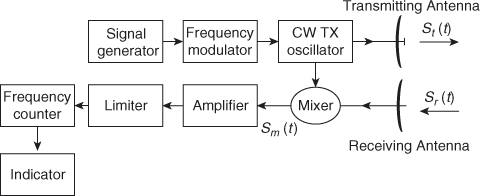
Branched Type Duplexers
Typical branched duplexer components are shown in the figure below. These duplexers were used during the World War II period and are still in use today. Branched type duplexer consists of ATR (anti-transmit receive) and TR (transmit-receive) switches, which are nothing but gas discharge tubes. In general, TR provides receiver protection and switching and ATR directs the echo power into the receiver. During transmission, both the ATR and TR switches get activated and provide very low impedances at the waveguide walls. Therefore, the transmitted signal energy passes through the antenna with minimum attenuation. During the transmission period, the TR unit protects the receiver by not allowing the transmitted signal leakage into the receiver channel.
During the reception, the signal from the antenna passes through the TR switch. On reception, the TR switch is in an inactive state (that is, it is matched to the transmission line impedance). Simultaneously, ATR is also in an inactive state to maintain high impedance to receive the signal in the direction of the transmitter, which leads to minimization of the loss of return signal energy in that direction. The advantages of the branched duplexer are simple, compact, and low cost. The disadvantage is limited operating bandwidth (about 5%) because element spacings are significant.

Nowadays branched duplexers are obsolete in all types of radars. Mostly circulator type duplexers are used in all radars as shown in the figure below. In the circulator type duplexer, the transmitter is connected at port 1, the antenna at port 2, and the receiver at port 3. When the transmitter sends a signal, the signal goes to the antenna with great ease and does not enter into the receiver because of the isolation of the circulator. When the signal comes back to the antenna, it goes directly to the receiver and not to the transmitter, because of the circulator operation.
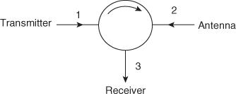
In radar, there should be zero isolation between the transmitter and receiver. It should be evident that to have the required isolation in the circulator, the transmitter, the receiver, and the antenna all must be well matched to the circulator. A still small part of the input signal emerges from port 3, and the ratio of this signal to the input signal is called isolation and it is expressed in decibels as:
I(dB)=10log_{10}\left ( \frac{P_{out3}}{P_{in1}} \right )
So, the transmitter is turned off while receiving the signals from the antenna and the receiver is turned off while transmitting the signals.
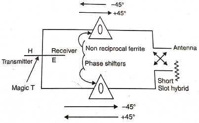
Ferrite Duplexer
There is some duplexer which uses the ferrite devices such as ferrite phase shifter, isolators, circulators to perform the duplexer actions. Instead of using the power-sensitive phase shifter in the phase shift duplexer. We may use a ferrite phase shifter. The ferrite duplexer uses a magic T, two non-reciprocal ferrite phase shifters and a short slot hybrid junction to perform the duplexer operation as shown in the figure below. The phase shifter provides the 450 phase shift either it advances the phase or it may retard the phase according to the directions of the energy flow. A TR may be used to protect the energy flow. A TR may be used to protect the receiver against leakage from the transmitter or reflected energy of the transmitter of an antenna. The ferrite duplexer has a lot of advantages over gas discharge tubs. It has wide bandwidth and fast recovery time than the gas discharge tubes. But it has a large size and weight and it requires a magnetic field for operations.