Table of Contents
DC Motor
A machine that converts mechanical power into d.c. electrical power is called a d.c generator. The same machine when used to convert d.c. electrical power into mechanical power is known as d.c. motor. From the construction point of view, there is no difference between a d.c. generator and motor.
The d.c. motors are very useful where a wide range of speeds and good speed regulation is required such as electric traction.
Induction Motor | Operation, Types, Application
Working Principle of DC Motors
The operation of DC motor is based on the principle that when a current-carrying conductor is placed in a magnetic field, a mechanical force is experienced by it. The direction of this force is determined by Fleming’s Left-Hand rule and its magnitude is given by the relation.
F = BIl newton
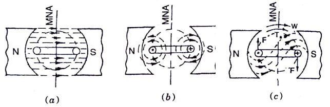
For simplicity, consider only one coil of the armature placed in the magnetic field produced by a bipolar machine [shown in the above figure (a)].
When d.c. supply is connected to the coil, current flows through it which sets up its own field as shown in the above figure (b).
By the interaction of the two fields (i.e. field produced by the main poles and the coil), a resultant field is set up as shown in the above figure (c). The tendency of this field is to come to its original position i.e. in a straight line due to which force is exerted on the two coil sides and torque develops which rotates the coil.
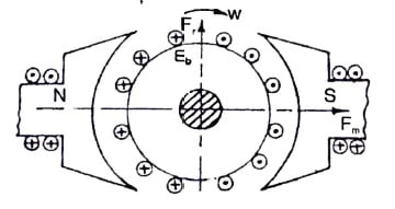
Alternatively, it can be said that the main poles produce a field Fm. Its direction is marked in the figure shown below. When current is supplied to the coil (armature conductors), it produces its own field marked as Fr. This field tries to come in line with the main field and an electromagnetic torque develops in the clockwise direction as marked in the figure shown below.

In an actual machine, a large number of conductors are placed on the armature. All the conductors, placed under the influence of one pole (say North pole) carry the current in the one direction (outward). Whereas, the other conductors placed under the influence of other poles carry current in the opposite direction as shown in the figure below . A resultant rotor field is produced. Its direction is marked by the arrow-head Fr. This rotor field Fr tries to come in line with the main field and torque (Te) develops. Thus, the rotor rotates.

It can be seen that to obtain a continuous torque, the direction of flow of current in each conductor or coil side must be reversed when it crosses the magnetic neutral axis (MNA). This is achieved with the help of a commutator.
Functions of commutator: The function of commutator in d.c. motor is to reverse the direction of flow of current in each armature conductor when it crosses the MNA to obtain continuous torque.
Back E.M.F.
It has been seen that when current is supplied to the armature conductors placed in the main magnetic field, torque develops and armature rotates, the armature conductors cut the magnetic field and an e.m.f. is induced in these conductors. The direction of the induced e.m.f. in the armature conductors is determined by Fleming’s Right-Hand Rule. It is marked in the figure shown below .
It can be seen that the direction of this induced e.m.f. is opposite to the applied voltage. That is why this induced e.m.f. in the armature, when the machine works as a motor, is called back e.m.f. (Eb). The magnitude of this induced e.m.f. is given by the relation;
E_{b}=\frac{PZ_{\phi }N}{60A}
A simple conventional circuit diagram of the machine working as a motor is shown in the above figure. In this case, the supply voltage is always greater than the induced or back e.m.f. (i.e. V > Eb). Therefore, the current is always supplied to the motor from the mains and the relationships among the various quantities will be;
E_{b}=V-I_{\alpha }R_{\alpha }Torque of a DC Motor
When a current-carrying current is placed in the magnetic field, a force is exerted or it which exerts turning moment or torque F x r. This torque is produced due to electromagnetic effect hence is called electromagnetic torque.
Since,
V=E_{b}+I_{\alpha }R_{\alpha }Multiplying both side by Ia, we get
VI_{\alpha }=E_{b}I_{\alpha }+I_{\alpha }^{2}R_{\alpha }i.e. Total electrical power supplied to the armature = Mechanical power developed by the Armature + loss due to armature resistance.
So, we can say that
Pm = Mechanical power developed by the armature = Fb Ia
Also, the mechanical power rotating armature can be given in terms of torque T and speed n.
i.e., P_{m}=\omega T=2\Pi nT.
where n in rps T in Newton-Meter.
For a particular D.C. motor, the no. of poles (P); No. of conductor per parallel path (Z/A) are constant
T=K\phi I_{\alpha }where K=\frac{ZP}{2\Pi A}.
Thus, It is concluded that torque produced in the armature is directly proportional to flux per pole and armature current, Moreover, the direction of electromagnetic torque developed in the armature depends upon the current in armature conductors. If either of the two is reversed the direction of torque produced is reversed and hence the direction of rotation. But when both are reversed and the direction of torque does not change.
Shaft Torque
In d.c. the motor whole of the electromagnetic torque (T) developed in the armature is not available at the shaft. A part of it is lost to overcome the iron and mechanical (friction and windage) losses. Therefore, shaft torque (Tsh ) is somewhat less than the torque developed in the armature.
Thus, in the case of d.c. motors, the actual torque available at the shaft for doing useful mechanical work is known as shaft torque.
Brake horsepower (B.H.P.)
In the case of motors, the mechanical power (H.P.) available at the shaft is known as brake horsepower (B.H.P.). If Tsh is the shaft torque in Nm and N is the speed in r.p.m. then,
Useful output power = ω Tsh = 2 πN Tsh /60 watts
and, Output in B.H.P. = =\frac{2\Pi N T_{sh}}{60\times 735.5}
Types of DC Motor
Similar to d.c. generators, on the basis of their field excitation, the also be classified as;
1. Separately excited DC motor: The conventional diagram excited d.c. motor is shown in the figure below. Its voltage equation will be;
E_{b}=V-I_{\alpha }R_{\alpha }-2v_{b}
2. Self-excited DC motor: These motors can be further classified as ;
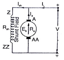
(i) Shunt motor: Its conventional diagram is shown in the figure below.
Important relations : I_{sh}=V/R_{sh};I_{\alpha }=I_{L}-I_{sh};E_{b}=V-I_{\alpha }R_{\alpha }-2v_{b}
(ii) Series motor: Its conventional diagram is shown in the figure below.
Important relations : I_{L}=I_{\alpha }=I_{sh};E_{b}=V-I_{\alpha }\left ( R_{\alpha }+R_{se} \right )-2v_{b}

(iii) Compound motor : Its conventional diagram is shown in the figure below.
Important relations: I_{sh}=V/R_{sh};I_{\alpha }=I_{L}-I_{sh};I_{se}=I_{\alpha };E_{b}=V-I_{\alpha }\left ( R_{\alpha }+R_{se} \right )-2v_{b}

In all the above voltage equations, the brush voltage drop vb is sometimes neglected since its value is very small.
The compound motor can be further subdivided as:
- Cumulative compound motor: In these motors, the flux produced by both the windings is in the same direction, i.e.,
- Differential compound motors: In these motors, the flux produced by the series field winding is opposite to the flux produced by the shunt field winding, i.e.,
Applications of DC Motor
As per the characteristics of d.c. motors, different types of d.c. motors are applied for different jobs as explained below :
1. Separately excited motors: Very accurate speeds can be obtained by these motors. Moreover, these motors are best suited where speed variation is required from very low value to high value. These motors are used in steel rolling mills, paper machines, diesel-electric propulsion of ships, etc.
2. Shunt motors: From the characteristics of a shunt motor we have seen that it is an almost constant speed motor. It is, therefore, used:
- where the speed between no load to full load has to be maintained almost constant.
- where it is required to drive the load at various speeds (various speeds are obtained by speed control methods) and any one of the speed is required to be maintained almost constant for a relatively long period.
As such the shunt motors are most suitable for industrial drives such as lathes, drills, grinders, shapers, spinning and weaving machines, line shafts in the group drive, etc.
3. Series motors: The characteristics of a series motor reveal that it is a variable speed motor i.e. the speed is low at high torque and vice-versa. Moreover, at light loads or at no-load, the motor attains dangerously high speed. It is, therefore, used:
- where high torque is required at the time of starting to accelerate heavy loads quickly.
- where the load is subjected to heavy fluctuations and speed is required to be adjusted automatically.
As such the series motors are most suitable for electric traction, cranes, elevators, vacuum cleaners, hair driers, sewing machines, fans, air compressors, etc.
4. Compound motors: The important characteristic of the motor is that the speed falls appreciably on heavy loads as in a series motor, but at light loads, the maximum speed is limited to a safe value. It is, therefore, used:
- where high torque is required at the time of starting and where the load may be thrown off suddenly.
- where the load is subjected to heavy fluctuations.
As such the cumulative compound, motors are best suited for punching and shearing machines, rolling mills, lifts, and mine-hoists etc.