Table of Contents
Microstrip Antenna
An antenna serves as the “communicator” between the RF front-end circuitry and the radiation and propagation of electromagnetic waves in free space. In microwave and other wireless applications, an antenna plays a very efficient job. Planar oriented antennas, such as microstrip patch and printed dipole have attracted significant attention of the community of antenna engineers because it’s excellent performance and a lot of benefits. This structure of antenna covers the modern wireless systems as compared to the conventional antenna designs.
At the last of 1970s, the international community of antenna design did a lot of efforts to the theoretical and experimental research on the microstrip patch antennas. Microstrip antenna is a very popular planer antenna with a simplest design. Due to its least complex structure, the design of patch in the microstrip antenna can be scratch with the help of etching method on a dielectric substrate is very simple. These antennas are:
- Low profile and Lightweight antennas.
- Most suited for space applications and cellular applications.
- Its integration is easy with electronic components.
- Its arrays can easily integrate.

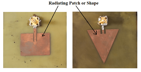
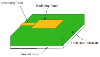
Microstrip antenna has a very thin metallic strip (patch) (t<< λ) generally or rectangular shape is placed on the above portion of the antenna. The patch structure and the ground plane are placed on the opposite phases of the antenna, and separated by a dielectric material sheet which is called as dielectric substrate. The radiating patch and the feed line are placed on the upper side of the antenna and these are fabricated by photo etched method on the dielectric substrate. The structure of radiating patch may be square, circular, elliptical, rectangular or any other shape. However, square, circular rectangular are mostly preferred because of the ease of analysis and fabrication. The feed line is also a metallic or conducting strip line normally of smaller width. Radiating patch is excited by the coaxial cable which has an inner conductor at the core of the cable are widely used.
The thickness of Microstrip antenna is generally very thin, the waves generated within the dielectric material (substrate between the patch and the ground plane) withstand reflections to some extent when they arrive at the corners of the strip, resulting radiation of only small fraction of the incident energy. Therefore, the antenna is considered to be very inefficient and it behaves more like a cavity rather than a radiator.
Characteristics of Microstrip Antenna
- Patch or microstrip antenna may be rectangular, circular, elliptical or many other regular shapes. Patch antenna is also known by different names like printed antenna or microstrip patch antenna or simply Microstrip Antenna (MSA).
- The patch antenna can be printed on a circuit board directly via etching.
- Microstrip antenna concept finally began to receive closer examination in the early 1970s when aerospace applications such as space craft and missiles produced the impetus.
- The radiating element and the feed lines are normally photo etched in the dielectric substrate.
- Between the patch and ground plane many dielectric substrates can be used and their dielectric constants generally in the range of .
- Linear or circular polarization can be done with either one element or arrays of patch antennas.
- Microstrip Antenna have a very high quality factor Q. The quality factor Q shows the energy losses related to the microstrip antenna.
- Thin dielectric substrates with high dielectric constants are mostly used for microwave circuitry.
Feed Techniques
Microstrip patch antenna has various methods of feeding techniques. There are few methods of feed techniques, which are popular or commonly used:
- Microstrip line (contacting feed technique)
- Coaxial probe (contacting feed technique)
- Aperture coupling
- Proximity coupling (non- contacting feed technique)
- Co planar wave guide feed.
Microstrip Line Feed
This is a type of feed technique. In which a metallic microstrip feed is directly connected to one side of the Microstrip patch as shown in Figure below. The main advantage of this technique is that, the feed is placed on same plane with the patch, so it is ease to fabricate.
Microstrip Line Feed
Coaxial Feed
This is a very common feed technique which is used in microstrip patch antenna. In this technique coaxial connector is used for feeding. The center conductor wire of the coaxial connector connected directly soldered to the radiating patch and the outer part of the conductor is soldered with the ground plane. The advantage of this feeding technique is that the feed point is placed at any point inside the radiating patch for matching with its input impedance.
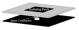
Coaxial Probe feed
Aperture Coupled Feed
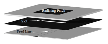
This is another technique of feeding, in which the ground plane is placed between the radiating patch and the feed line. A slot is used for providing connection between the patch and the feed line. This technique is not used frequently because of its difficult fabrication of multiple layers, which increase antenna thickness.
Aperture-coupled feed
Proximity Coupled Feed
Another name of this technique is electromagnetic coupling technique. In this technique the feed line is placed between the two dielectric substrates and the radiating patch is placed on the top of the upper substrate.

Proximity-coupled Feed
Advantages of Micro-strip patch antennas
Some of their main benefits are:
- Light weight and low volume.
- Low creation cost, subsequently can be produced in substantial amounts.
- linear and circular polarization, supports both,.
- Can be effectively coordinated with microwave integrated circuits (MICs).
- Capable of double and triple frequency operations.
- Micro-strip antennas are moderately cheap to produce and design as a result of the basic 2-dimensional physical geometry.
- Easy to print an array of patches on a one substrate utilizing lithographic systems.
Disadvantages of Micro-strip Patch antennas
- Micro-strip patch antennas suffer from more drawbacks as compared to conventional antennas. Some of the main drawbacks are:
- Bandwidth is narrow.
- Efficiency is low.
- Low Gain
- Extraneous radiation from feeds and junctions
- Poor end fire radiator
except tapered slot antennas - Low power handling capacity.
- • Surface wave excitation
Application of microstrip antenna
Some of the applications for the Micro-strip Patch Antenna are as follows
- Radio altimeters
- Command and control system
- Remote sensing and environmental instrumentation
- Feed element in complex antennas
- Satellite navigation receivers
- Mobile radio
- Integrated antennas
- Doppler and other radars.
- Used in GPS (Sattelite Navigational System) technology.
- Mobile satellite communications, the Direct Broadcast Satellite (DBS) system & remote sensing.
- Non-satellite based applications- such as medical hyperthermia.
Related Posts: