Table of Contents
Klystron Amplifier
To remove the limitation of traditional tubes, microwave tubes are constructed. Microwave tubes take a large transit time for the required operation. The basic principle of operation of the microwave tubes involves a transfer of power from a source of DC voltage to a source of AC voltage by means of a current density modulated electron beam. The power transfer operation is done due to the accelerating electrons in a static electric field and retarding them due to the AC field.
There are many types of microwave tubes; those are different from each other in terms of their mechanics of producing density modulation, acceleration and the retardation of electrons by short gap over an extended region. A Klystron tube is generated the microwave frequencies, this can be used as amplifier or oscillator of the microwave signals. Klystron was developed by Russell H Varian at Stanford University in 1939, in association with his brother SP Varian.
Two Cavity Klystron Amplifier
The klystron tube is also known as a
Operation

The RF signal is used as an input in the buncher cavity for excitation or amplification of signal, which will produce an alternating voltage of signal frequency across the gap A. The bunches of electrons will produce due to this input voltage which will applied in gap A. These bunches of electrons are also known as velocity modulation of free electron beam. The process of velocity modulation or bunching is explained with the help of apple gate diagram.

In the apple gate diagram, each line represents distance-time history of an individual electron, the slope of each line being inversely proportional to the velocity of the electron it represents. Electrons entering the cavity at time instants A, B and C experience a zero value of the RF field and therefore travel without any change in velocity, these electrons are called as reference electrons er which will travels at normal velocity
Where V is the anode to cathode voltage.
At point E of the RF cycle, some electrons will pass through gap A, these electrons are called as late electrons (el) because these electrons cross the gap after the reference electrons (er). But these electrons are subjected to maximum positive RF voltage, and they are traveling faster than the reference electron with an increased velocity (V>V0).
Similarly, at point D, the input signal has maximum negative voltage and produces deceleration/ retardation of the electron (called as early electron ee). Due to this retardation, early electron will move at a lower velocity (V<V0), and reference electron el catches up with early electron, similarly, later electron el, which moves at a faster rate (V>V0) tries to catch up with reference electron.
Applications
Used as an amplifier in UHF TV transmitters, satellite communication ground station, radar transmitters etc.
It is also used as an oscillator.
Multicavity Klystron
Limited gain is available for a two-cavity klystron amplifier. This limitation cab is overcome connecting several two-cavity tubes in cascade, feeding the output of each tubes to the inputs of the succeeding one. Four cavities are cascaded to form four cavity system is shown in the figure.
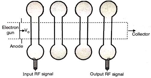
In this cavity system, each transitional cavity work like a buncher with the passing electron beam, including an amplifier RF output than the past cavity.
For narrowband applications, the whole cavities are tuned to the same frequency, called synchronous tuning.
Reflex Klystron Oscillator
A reflex klystron is another type of klystron tube. In this tube only one cavity is used as a resonator and operates as an oscillator/ microwave generator of low power and low frequency.
It is mostly used in various frequency applications
- Radar receivers
- Microwave links
- In parametric amplifier as a pump oscillator
- Local oscillator in microwave receivers.
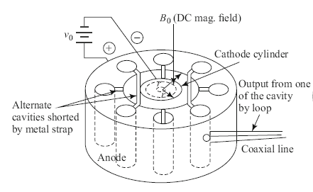
The inner arrangement of reflex klystron is shown in the figure. Many sections are present in the reflex klystron, those are electron gun, resonator cavity, repeller, and output coupling. The repeller electrode is connected with a negative voltage and it reflects the partially bunched electron beam back to the resonator cavity. This provides a positive feedback mechanism which supports oscillations. Thus under suitable conditions, the electrodes give more energy to the gap than took from the gap.
Operation
The operation of reflex klystron is a little bit different from the two-cavity klystron because there is only one cavity. This single cavity is work like a buncher as well as catcher cavity. First of all, consider an electron A which passes through the resonator gap when the voltage across the gap is zero.
This electron velocity is unaffected by the gap voltage. This electron reflected back to the resonator cavity after some time. After that next electron B passes through gap ∆t time earlier. Since gap voltage is positive at this instant, the initial velocity V0 for this electron is higher than the average value (that of electron A). This electron will faster in the repeller or drifts space and take a longer time to come back to the resonator. It would make a bunch with electron A. Similarly an electron C, which passes through the gap ∆t time after A, appears with a smaller initial velocity and so takes less time to come back. So, this electron C also combined in the bunch with electron A.