Table of Contents
Semiconductor Optical Amplifiers (SOA)
A semiconductor optical amplifier (SOA), also known as a laser amplifier, is an active medium of a semiconductor laser. In other words, an SOA is a laser diode without or with very low optical feedback. An electric current is externally applied to the laser device that excites electrons in the active region. When photons travel through the active region it can cause these electrons to lose some of their extra energy in the form of more photons that match the wavelength of the initial ones. Therefore, an optical signal passing through the active region is amplified and is said to have experienced optical gain.
So we can say that semiconductor laser can act as a semiconductor optical amplifier when operating quite close to its threshold value.
Operation of Semiconductor Optical Amplifiers (SOA)
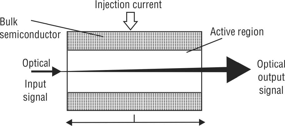
The principle of stimulated emission is primarily used by a semiconductor optical amplifier for amplification of an optical information signal, as the case with laser operation. The figure below depicts the principle of operation of SOA.
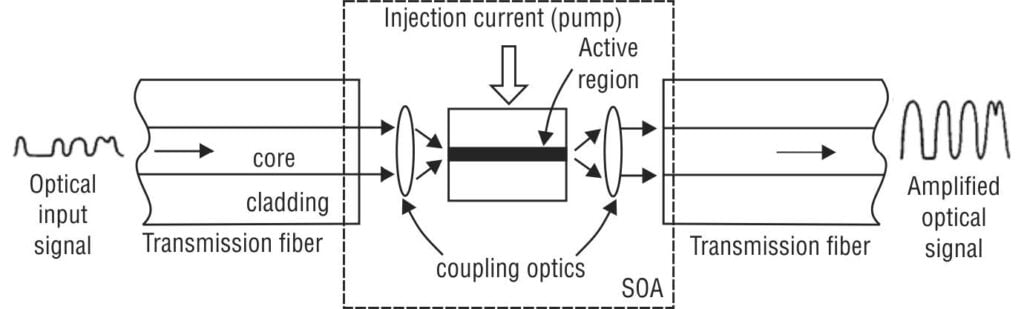
As shown, the injection current (also termed as pump signal) in the active region to achieve population inversion is actually responsible for the desired optical gain. The coupling optics is used at the input and output of the active region to couple it efficiently with transmission fiber on either end of the active region. The optical gain depends on the following factors:
- the wavelength of the optical input signal
- the type and characteristics of the amplifier medium (active region)
- the local beam intensity at any point within the active region
Types of Semiconductor Optical Amplifiers (SOAs)
Based on the structure, there are two types of semiconductor optical amplifier such as
- Fabry–Perot Laser Amplifier (FPLA)
- Traveling–Wave Semiconductor Laser Amplifier (TWSLA)
Fabry–Perot Laser Amplifier (FPLA)
It has the same configuration as that of Fabry–Perot laser, as shown in figure below.
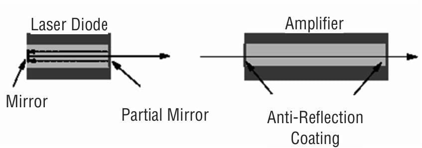
Fabry–Perot laser amplifiers are almost identical to regular index-guided Fabry–Perot lasers. Either edge (or “facets”) of the SOA are designed to have very low reflectivity so that there are no unwanted reflections of the signal within the semiconductor itself. The main difference from regular lasers is that they have reflective facets in order to build up the intensity of light within the semiconductor material. Whereas in the FPLA, the back facet is pigtailed. The figure below shows the basic configuration depicting principle of operation of FPLA.
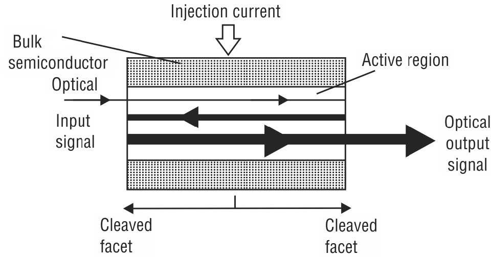
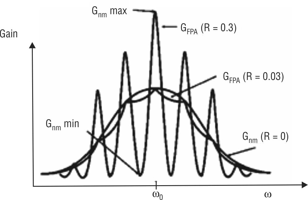
As seen, the input optical signal that enters the active region is reflected several times from cleaved facets on both sides of the active region. When the signal leaves the cavity, it is amplified. The FPLA (or, FPA) is biased below the normalizing threshold current gain. The figure below shows typical characteristic curves of optical gain versus frequency for various values of facet reflectivity, R.
Traveling–Wave Semiconductor Laser Amplifier (TWSLA)
In a traveling–wave semiconductor laser amplifier (TWSLA), or simply TWA, an input optical signal is amplified by a single passage through the active region. There is no optical feedback possible as it does not have any reflective facets. The figure below shows the basic configuration depicting principle of operation of TWSLA.
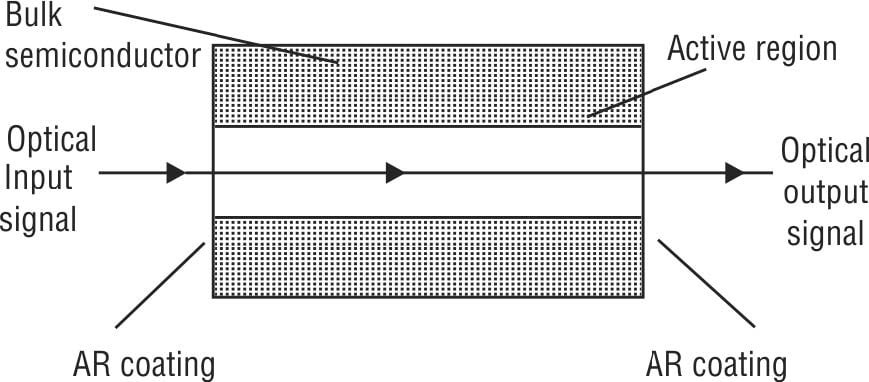
In TWSLA, the Fabry–Perot cavity resonances must be suppressed. To accomplish this, the reflectivity must be reduced. There are three different approaches that are commonly used:
TWSLA using antireflection (AR) coating (reflectivity of ~ 10-4)
TWSLA using tilting active region
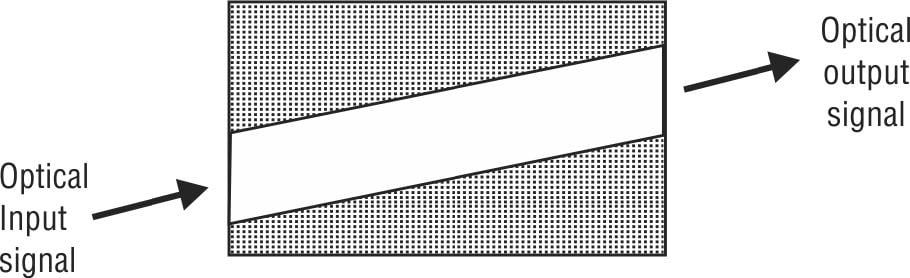
The optical input signal enters the angled facet at one end of the active region, follows the path and leaves it at the other end as optical output signal. In this way, the reflected beam is physically separated from forward beam, thereby achieving reflectivity figure of ~ 10-3 to 10-4.
TWSLA using transparent window region
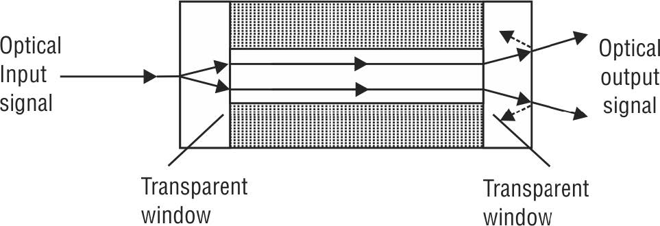
Here the optical input signal (light beam) at one end of the active region spreads in the first transparent window region and then enters at the semiconductor–air interface. It travels straight through the medium (thin active region surrounded by bulk semiconductor material) up to the second transparent window region. Then the spread optical output signal is available at the other end of the medium. Due to further spreading of the reflected beam on the return trip, there may not be much coupling of light into the thin active region.
Performance Parameters of Semiconductor Optical Amplifiers (SOAs)
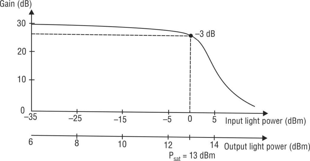
Semiconductor optical amplifiers saturate and the typical saturation output power for SOAs is around 5–10 mW, as shown in the figure below.
The performance of semiconductor optical amplifiers can be measured in terms of gain, noise, bandwidth, and dependence on polarization. The detailed analysis of these performance parameters as well as comparison between Fabry–Perot and Traveling–Wave semiconductor optical amplifiers is presented here.
Gain as a function of angular frequency
We know that
G_{FPA}(\omega )=\frac{G_{s}(\omega)[(1-R)^{2}]}{[1-RG_{s}(\omega)]^{2}+4RG_{s}(\omega)\sin^{2}[\frac{(\omega -\omega _{0})L}{\upsilon }] } G_{TWA}(\omega )=G_{s}(\omega)=e^{[(\Gamma g-\alpha )L]}It is worthwhile to mention here that the value of Gs (w) depends on the state of polarization of the input optical signal. The confinement factor Γ and the gain coefficient g also depend on the state of polarization because of rectangular shape and crystal structure of active region.
Noise generated by SOA
Spontaneous emitted and amplified photons constitute amplified spontaneous emission (ASE) in an optical amplifier. This phenomenon generates the noise in its active medium. Since they are random in phase and direction, they generate noise within the signal’s bandwidth. Spontaneous-emission factor (nsp), also termed as population-inversion factor, is defined as the ratio of population of excited energy levels and the difference between the populations of excited and lower energy levels.
n_{sp}=\frac{N_{2}}{N_{2}-N_{1}}where, N2 and N1 are populations of excited and lower energy levels, respectively.
Optical bandwidth of SOAs
By definition, the bandwidth of an amplifier is the difference between the maximum and minimum frequency at which the gain falls by 3 dB from its maximum value. The bandwidth of FPLA and TWSLA are given as
BW_{FPLA}=(\omega -\omega _{0})=\frac{\nu }{L}\sin ^{-1}\left (\frac{1-RG_{s}}{2\sqrt{RG_{s}}} \right )\approx \frac{c}{L}\sqrt{\frac{(1-R)^{2}}{R}}\times \sqrt{G_{FPA}(max)} BW_{TWSLA}\approx \frac{c}{L}\sqrt{\frac{(1-R)^{2}}{R}}\times \sqrt{G_{s}}Polarization dependence of SOAs
The optical gain of SOAs depends on the state of polarization of the input optical signals, i.e., the amplification of TE and TM modes is different. This is due to the rectangular shape and the crystal structure of the active region, which make gain-coefficient (g) and confinement factor (Γ) dependent on polarization. The difference in gain between two orthogonal polarizations can be 5–7 dB. The polarization dependence in SOAs can be reduced in following ways:
- Make active region as square as possible in cross-section.
- Connect two SOAs in series or in parallel to compensate for unequal gain in ortho–polarization.
- A double pass through same active region.
Advantages of SOAs
- The optical gain provided by SOAs is relatively independent of wavelength of the incident optical signal.
- The injection current serves as the pump signal for amplification, not another laser.
- Due to compact size, SOAs can be integrated with several waveguide photonic devices on a single planar substrate.
- They use the same technology as diode lasers.
- SOAs have the ability to operate at operating wavelengths of 1300 nm and 1550 nm with wider bandwidth (up to 100 nm).
- They can be configured and integrated to function as pre-amplifiers at the optical receiver end.
- SOAs can function as simple logic gates in WDM optical networks.
Limitations of SOAs
- SOAs can deliver output optical power up to a few mW only which is usually sufficient for single channel operation in a fiber–optic communication link. However, a WDM system may require up to a few mW power per channel.
- Since coupling of the input optical fiber into the SOA integrated chip tends to induce signal loss, SOA must provide additional optical gain in order to minimize the impact of this loss onthe input facet of the active region.
- SOAs are highly sensitive to polarization of the input optical signal.
- They generate higher noise level in the active medium.
- In case multiple optical channels are amplified as required in WDM applications, SOAs can produce severe crosstalk.

