Table of Contents
Printed Circuit Board
The printed circuit board (PCB) is an electronic component base where various components placed and solder. A PCB is made by etching the copper layer on the board as the layout of the circuit diagram. There are different methods of doing this, but the most common one is based on using a ferric chloride solution. If this etching process is not done properly, then shorting of adjacent traces may occur. Many times the shorting is due to the incorrect layout designed on the copper plate. Finding a shorting on a PCB can become very challenging if the board is completely etched and has very thin lines of connections between various components.

So testing of continuity is a very important task of PCB before the insertion of various components, those are used in the circuit.
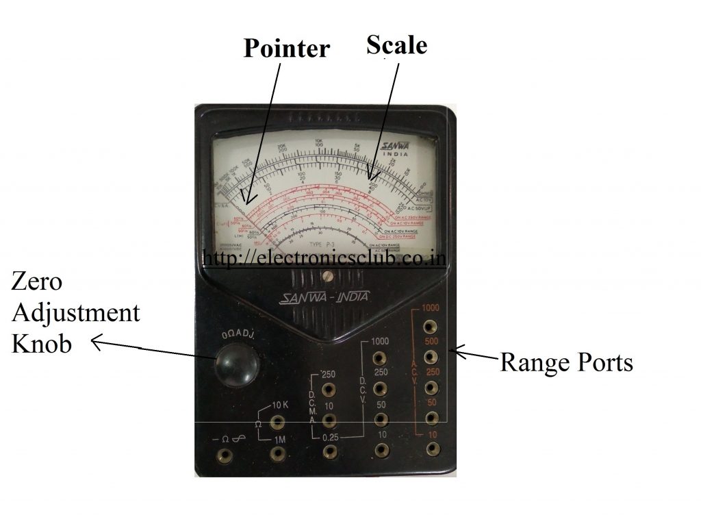
MultiMeter
The multimeter is widely used in every measurement techniques. With the help of multimeter, we can measure various quantities such as resistance, AC & DC voltage, current, capacitance, etc. A multimeter is a voltmeter, ammeter, and millimeter combined together. There, it is also known as VOM (Volt-Ohm Millimeter). A multimeter may likewise have different capacities, for example, diode testing, coherence test, transistor test, TTL rationale test, and recurrence test.
Important Points for continuity testing of PCB –
- Firstly check the PCB traces under the microscope or magnifying glass. See if you can find any traces that look short. Identify all suspicious places on the board with sorting is done and mark that places with the help of a marker. Try avoiding these shorting where you marked. You can place marks on nearby components or on ground or supply planes.
- If a circuit diagram is available, find the traces or shorting places those you marked as suspicious on the diagram. Check if these shorting points should be separate or connected. In some cases, traces are deliberately connected. Go through all suspicious shorting points and remove the ones that are connected in the circuit diagram. If the circuit diagram is not present there, skip this step.

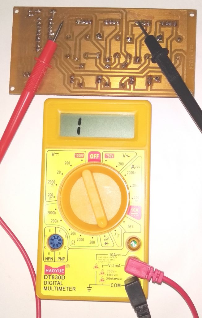
- Insert the red Multimeter lead plug into the “V” socket of the millimeters and the black lead plug into the “COM” socket. Place the multimeter knob to the continuity test position. This position generally has a sign with several small parallel lines and a diode icon.
- Turn on the multimeter. Test the multimeter continuity tester by touching its two leads together. This should produce a continues to beep. If it does not beep, you have not set the knob to the continuity testing position, or the check the battery may need to be replaced.
- Connect the first probe of multimeter at one end and second probe on the last point of the suspicious traces. It does not matter what is the polarity of connections. You will have to press strongly to make the electrical connection between the multimeter probes and the traces. If a beep sound produces, there is a short. Repeat this process for all suspicious traces.
A PCB, or Printed Circuit Board, contains a large number of electronic components that are interconnected through thin copper traces. The distance between these traces is generally very small, on the order of less than 1/2 millimeter. Such a short distance makes the side-by-side traces prone to short, which is getting electrically connected with one another. An electrical short in a circuit may obstruct its proper working, make it nonfunctional or damage its one or more components.