Table of Contents
Radar Modulator
Radar Modulator: A modulator is a heart in the transmitter. it not only controls the radiofrequency energy to be produced in sharp pulses but also controls the repetition frequency and shape of the pulse. The modulator is the device that turns the transmitting tube on and off in such a manner as to generate the desired waveform. When the transmitted on the waveform is a pulse, the modulator is sometimes called pulser. Each RF power tube has its own particular characteristics, which determine the type of modulator.
Types of Radar Modulator
Pulse modulators are divided into two categories and they are
- Grid Modulators
- Anode Modulators
Grid modulators are not employed at present due to the following reasons:
- A grid modulator requires high H.T. to be maintained longer time than an anode modulator.
- More precise control is possible with anode modulation.
- Transmitter valves like magnetrons used at centimeter wavelengths do not have control grid.
Anode modulators can be further classified as Soft Valve Modulators and Hard Valve Modulators.
Basic Elements of the Radar Modulator
A simple block diagram of a radar modulator is shown in the figure below. It consists of an energy source, charging impedance, a switch, and an energy storage circuits. Energy that is supplied externally accumulates in the storage devices at a slow rate during the period of interpulse. The purpose of charging impedance to restrict the rates at which energy can be delivered to the storage devices. The switch is closed when the pulse is formed and the accumulated energy rapidly discharged through the load. The load may be a magnetron valve. The charging impedance prevents the energy to dissipate from the storage elements to the source, during the discharge period.

Three basic types of radar modulator used for magnetron oscillator
- The line -type modulator with a gas tube switch and a delay line storage element.
- The pulsactor, which uses saturable reactances for both switching and storage purposes.
- The hard tube modulator incorporating a vacuum tube switch and capacitor storage elements.
Line-Type Modulator
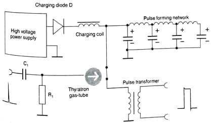
The modulator containing a gas tube switch and a delay line as the energy storage element is called a line type modulator as shown in the figure below. It is commonly employed with high power magnetron. The delay line of the line type modulator is called the pulse-forming network (PFN).
Radiofrequency energy in radar is transmitted in short pulses with time durations that may vary from 1 to 50 microseconds or more. A special modulator is needed to produce this impulse of high voltage. The hydrogen thyratron modulator is the most common radar modulator As circuit for storing energy the thyratron modulator uses essentially a short section of artificial transmission line which is known as the pulse-forming network (PFN). Via the charging path this PFN is charged on the double voltage of the high voltage power supply with help of the magnetic field of the charging coil. Simultaneously this charging coil limits the charging current. The charging diode prevents that the PFN discharge its own about the intrinsic resistance of the power supply again.

The function of the thyratron is to act as an electronic switch, which requires a positive trigger of only 150 volts. The thyratron requires a sharp leading edge for a trigger pulse and depends on a sudden drop in anode voltage (controlled by the pulse-forming network) to terminate the pulse and cut-off the tube. The R-C Combination is acting as a DC shield and protects the grid of the thyratron. This trigger pulse initiates the ionization of the complete thyratron by the charging voltage. This ionization allows conduction from the charged pulse-forming network through a pulse transformer. The output pulse is then applied to an oscillating device, such as a magnetron.
The Charge Path
The thyratron is an open circuit between the trigger Pulses, Therefore in the figure below. it is shown as an open switch.

After the power supply switching on, the current flows through the charging diode and the charging coil and charges the condensers of the pulse forming network (PFN). However, the induction of the charging coil offers a great inductive resistance to the current and builds up a strong magnetic field. The charging of the condensers follows an exponential function. The sell- induction of the charging coil overlaps for this.

The above figure shows the Charging curve of PFN. If the condensers are charged with the power supplies voltage, decreases the current and the magnetic field breaks down. The breaking down magnetic field causes an additional induction of a voltage. This one continues the charging of the condensers up to the double voltage of the power supply. Now the condensers would discharged about the power supplies resistance, but the charging diode cut-off this current direction and the energy remains stored therefore in the condensers.
The Discharging Path
The Discharging Path of the modulator shown in the figure below. When a trigger pulse is applied to the grid of the thyratron, the tube ionizes causing the pulse-forming network to discharge through the thyratron and the primary of the pulse transformer.

The above figure shows the Discharging curve of PFN. The first condenser begins the discharge. This one would happen like an exponential function, but the other condensers recharges the first one, delayed by the PFN-coils.
For the duration PW, a current flows through the pulse transformer, therefore. The high voltage pulse for the transmitting tube can be taken on the secondary coil of the pulse transformer. Exactly for this time an oscillating device swings on the transmit frequency. Because of the inductive properties of the PFN, the positive discharge voltage has a tendency to swing negative. If the oscillator and pulse transformer circuit impedance is properly matched to the line impedance, the voltage pulse that appears across the transformer primary equals one-half the voltage to which the line was initially charged.
The magnetron is non-linear impedance and will not be matched to the line under all conditions. The mismatch can cause a spike to appear at the leading edge of the pulse. The spike can be minimized by introducing an RC circuit in parallel with the primary of the pulse transformer. This is called the De-spiking circuit. The resistance is chosen equal to the impedance of the PFN, and the capacitance is chosen small enough so as to be almost completely charged after the oscillator draws full-load current.
The function of damping network is to help to reduce the trailing edge of the voltage pulse and prevent post pulse oscillations, which could introduce noise or false targets. The damping network consists of a resistance and a inductance in series at the secondary of the pulse transformer.
Thyratron
A typical thyratron is a gas-filled tube for radar modulators is shown in the figure below. The function of the high-vacuum tube modulator is to act as a switch to turn a pulse ON and OFF at the transmitter in response to a control signal. The grid has complete control over the initiation of cathode emission for a wide range of voltages.

The anode is completely shielded from the cathode by the grid. Thus, effective grid action results in very smooth firing over a wide range of anode voltages and repetition frequencies. Unlike most other thyratrons, the positive grid-control characteristic ensures stable operation. In addition, using the hydrogen-filled tube reduces deionization time.
A trigger pulse ionizes the gas between the anode and the cathode. Only by removing the plate potential or reducing it to the point where the electrons do not have enough energy to produce ionization will tube conduction and the production of positive ions stop. Only after the production of positive ions is stopped will the grid be able to regain control. Because of the very high anode voltage, the anode is attached most on the upper end of the glass bulb. Therefore the tube looks very ancient.
Saturable-Reactor Modulator
The saturable reactor is an iron core inductance and it is so designed that its magnetic core is driven into saturation for normal values of current in the coil. When the current flowing through the coil is small and the core is unsaturated then the incremental inductance is high.
And when the inductances is low for high currents when the core is saturated. The saturable reactor has relatively long life than other radar modulators. It is not using either any mechanical part or any electronic tubes. It has one main draw back that it cannot control the pulse shape results in poor and uncontrolled pulse shape.
A two-stage saturable-reactor modulator or a pulsactor is shown as below.

Hard-tube Modulator
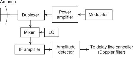
The hard valve modulator the switching is accomplished with hard vacuum tubes instead of soft gas tubes. Basically, it is a high-power video pulse generator. A block diagram of a particular hard tube modulator is shown in the figure below. The trigger pulses initiate the driver at the proper instants of time. The driver generates the desired pulse wave shape. The power amplifier is being used to amplify the waveform generated by the driver, to the level that requires pulsing the transmitter. There are many numbers of pulse-forming circuits, which could is for the driver. The video amplifiers using high power tubes are being used as power amplifiers. A single high-power tube working as a blocking oscillator can be used as a pulse modulator. A blocking oscillator is a self-excited, overdriven oscillator.

A major limitation of the hard tube modulator in the past has been the lack of vacuum tubes capable of handling the large power required for pulsing big radar transmitter.
Comparison of Radar Modulator with Magnetron Modulator
- The Line-type modulator is simple and efficient. Due to its small size and lightweight, it is desirable in airborne radar. The problem with this modulator is pulse changing of pulse duration from pulse to pulse, which requires switching to another pulse forming network.
- The saturable reactor has the advantage of no active elements, it has a long life. it is more difficult to control the shape of the pulse in this modulator.
- The hard tube modulator can change pulse duration, pulse shape, or PRF with little effort. It may be used to generate a group of pulses. it is less efficient than the others but provides the greatest flexibility in operation.
Related Post: