Table of Contents
Directional Couplers
Directional couplers are flanged, built-in waveguide assemblies which can sample a small amount of microwave power for measurement purposes. They can be designed to measure incident and/or reflected powers, SWR (Standing Wave Ratio) values, provide a signal path to a receiver or perform other desirable operations. They can unidirectional (measuring only incident power) or bi-directional (measuring both incidents and reflected) powers. In its most common form, the directional coupler is a four-port waveguide junction consisting of a primary main waveguide and a second auxiliary waveguide.
In general directional couplers are the four-port junction for sampling or taping the power flow using secondary auxiliary waveguide, without disturbing the main primary waveguide line power. Therefore some directional couplers are unidirectionally meant for measuring incident power, while some directional couplers are bidirectional for measuring both incident and reflected power.
The directional coupler is a 4–port reciprocal device. Direction couplers consist of two transmission lines and a mechanism for coupling signals between them. Let us understand the meaning of the two terms (viz.coupler and directional) in the directional coupler.
Coupler
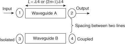
A coupler is a device that consists of two waveguides which are placed very close to each other as shown in the figure below. Thus, a portion of energy traveling in waveguide A will be coupled on waveguide B. We can make this coupler directional by using a specific length (L) of the transmission line.

Directional
The term directional means the energy is passed in one direction only, and no energy passes in the reverse direction. The directional property is obtained by using a specific length (L) of a transmission line, that is, a quarter wavelength (λ/4). A λ/4 transmission line offers high impedance at one end and low impedance at the other end. Therefore, the specific length (L = λ/4 or (2n + 1) λ/4) makes a coupler directional over a certain band of frequency as shown in the figure below.
Power flow in a directional coupler:
The power incident at port 1 (input) is split between two other ports ( port 4 (coupled) and port 2 (output)), and no power appears from port 3 (isolated). The power flow in a directional coupler is shown in the figure below.
Pi or P1 = power incident at port 1
Pf or P2 = forward power or output power at port 2
Pb or P3 = reflected power at isolated port 3 in the secondary waveguide
Pfc or P4 = forward coupled power in the secondary waveguide, that is, at port 4

The properties of an ideal directional coupler are as follows:
- In an ideal directional coupler, all the four ports are perfectly matched and also ports1,3 and ports 2, 4 are perfectly isolated.
- A portion of the wave is coupled to port 4 but not coupled to port 3 which is traveling from port 1 to port 2. Similarly, a portion of the wave traveling from port 2 to port 1 is coupled to port 3 but not to port 4.
- Likewise, the portion of the wave traveling from port 4 to port 3 is coupled to port 1 but not to port 2. Similarly, a portion of the wave traveling from port 3 to port 4 is coupled to port 2 but not to port 1
- The coupling between port 1 and port 4 is similar to that between port 2 and port 3, and the degree of coupling depends on the structure of the coupler.
- The outputs are always in phase quadrature; that is, they exhibit a phase difference of 900. For this reason, a directional coupler is called a quadrature-type hybrid.
Directional Coupler Parameters
A directional coupler is characterized by 3 parameters:
- Coupling factor
- Directivity
- Isolation
Coupling factor (C):
The coupling factor of a directional coupler (DC) is defined as the ratio of the incident power (Pi ) to the forward power (Pf ) measured in dB. It indicates the fraction of input power coupled to the coupled port.
C=10 log_{10}(\frac{P_{i}}{P_{f}})dB=10 log_{10}(\frac{P_{1}}{P_{4}}) dBwhere P1 is the power incident at port 1, and P4 is the power coupled at port 4.
Directivity (D)
Directivity of a DC is defined as the ratio of forward power (Pf ) to the back power (Pb ) expressed in dB. Directivity is the ability to isolate coupled (port 4) and backward (port 3) ports.
D=10 log_{10}(\frac{P_{f}}{P_{b}})dB=10 log_{10}(\frac{P_{4}}{P_{3}}) dBIsolation (I)
Isolation is defined as the ratio of power incident (Pi ) to the power coupled in the isolated port (Pb ) and is expressed in dB.
I=10 log_{10}(\frac{P_{i}}{P_{b}})dB=10 log_{10}(\frac{P_{1}}{P_{3}}) dBIn an ideal directional coupler, D and I are infinite (as P3 = 0), and C is of the order of 10 dB.
Note: The coupling factor is a measure of how much of the incident power is being sampled while directivity is a measure of how well the directional coupler distinguishes between the forward and reverse traveling powers. Isolation in dB equals coupling factor plus directivity.
Types of directional couplers:
There are two types of directional couplers; both are four-port components and are reciprocal.
- Two-hole directional coupler
- Single-hole or Bethe-hole directional coupler
Two-Hole Directional Couplers
The two-hole directional coupler is mostly used in all applications. The directional coupler consists of two waveguides referred to as the main waveguide with ports 1 and 2 and an auxiliary waveguide with ports 3 and 4. When power is applied at port 1 of the main waveguide, the output is taken at port 2 of the main waveguide.
A fraction of the power is coupled into port 4 of the auxiliary waveguide, and no power flows in port 3 of the auxiliary waveguide. Since the device is reciprocal, the power incident in port 3 of the auxiliary waveguide flows in port 4, a fraction of the power couples in port 2, and no power flows in port 1 of the main waveguide. To have the directional property of a coupler, the spacing between the centers of two holes should be L= (2n + 1) λ/4, where n is any positive integer. The hole acts as a slot antenna. A portion of the wave energy entering into port 1 passes through holes and radiates into the secondary guide.

Bethe-hole Directional Couplers
This is the simplest form of a waveguide directional coupler. In the Bethe-hole coupler, two waveguides are placed one above the other. A hole is located at the center of a common broad wall of two waveguides. The two waveguides are placed at an angle, θ as shown in the figure below.
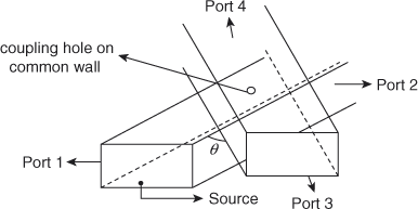
The input is incident at port 1 of the main waveguide (i.e. lower waveguide). The mode of propagation is the TE10 mode. If the hole (or aperture) is small compared with the propagating signal wavelength (λ), the hole acts similar to an electric dipole that is normal to the aperture plane. This dipole moment is a function of the normal component of the electric field in the main waveguide and the tangential component of the exciting magnetic field at the aperture. Due to radiation from this dipole, coupling to the auxiliary guide is achieved.
Applications of Directional Couplers
Directional couplers are extensively used in systems that measure the amplitude and phase of traveling waves. The major applications are as follows:
- Power monitoring and source leveling
- SWR measurements
- In unidirectional power measurements
- In reflectometers
- Unidirectional wave launching
- Isolation of signal sources