Table of Contents
DUAL TRACE CRO
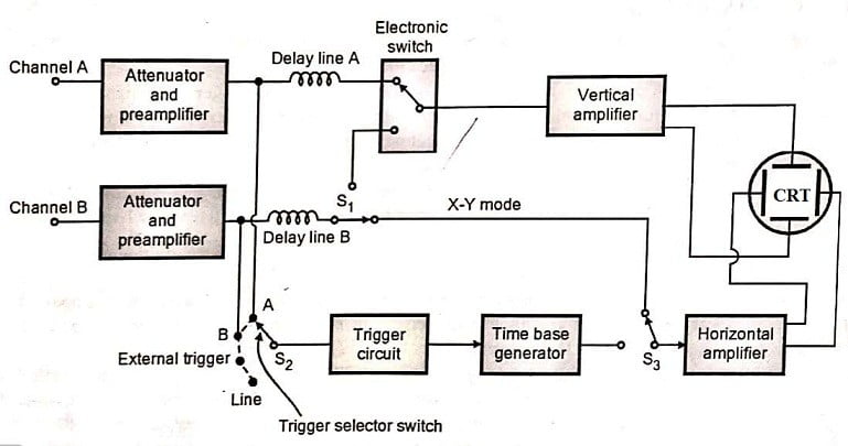
In dual trace CRO, two separate vertical input signals can be displayed simultaneously. The CRO consists of a single beam CRT, single time base generator, and two identical vertical amplifiers with an electronic switch. The output of the vertical amplifiers is connected to the electronic switch via a mode control switch.
Dual trace CRO is used to generate only one electron beam but display two traces. Thus the same electron beam is used for generating both the traces to display two different input signals simultaneously.
Block Diagram of Dual Trace CRO
There are two separate vertical input channels, channels A and B. They use separate attenuator and preamplifier stages. Because of this arrangement, it is possible to control the amplitude of each input independently.
After amplification, both the channels are applied to an electron switch. This switch will connect one channel at a time to the vertical amplifier via a delay line.
The trigger selector switch S2 allows the circuit to be triggered by channel A or channel B or line frequency or signal from an external source.
The Horizontal amplifier gets input either from channel B or from time base generator through switch S1 and S3 depending on the mode of operation.
Only in X-Y mode of operation, the input of the horizontal amplifier is from channel B. Otherwise it gets input from time base generator.
In X-Y mode of operation, the time base generator is disconnected from the horizontal amplifier and channel B acts as horizontal input. Channel A acts as a vertical input. It plots Y-input (Channel A) with respect to X-input (Channel B).
It allows two modes of operations:
- The alternate mode.
- The chopped mode.
Alternate Mode (ALT Mode)
In the alternate mode, the electronic switch connects the two channels A and B alternately in the successive cycles of the time base generator. Thus two channels are alternately connected to the vertical amplifier.
The switching rate of the CRT is controlled by the sweep rate of the time base generator. Hence, the CRO alternately displays the two vertical signals. Each vertical amplifier has its own calibrated input alternators and position controls so that the amplitude of each signal can be separately adjusted.
The alternate mode is used for the high-frequency signal. Timebase is set at high speed so that both the traces appear as continuous traces instead of alternate traces.
Chopped (Chop) Mode
In the chopped mode, the electronic switch will make several transitions from one channel to the other during one sweep.
A free-running oscillator is used to control the position of the electronic switch.
As the electronic switch is running at a very high speed, each channel is displayed for a very short time.
The switching rate of the electronic switch or chopping rate is approximately 100 kHz or 0.01 msec.
This is of greater use for simultaneous observation of the low-frequency signals, whose frequency is much lower than the chopping frequency.
Dual Beam CRO
The dual-beam CRO is built around a special CRT, which displays two completely independent beams.
It has two separate electron beams. Each electron beam has its own independent sets of vertical and horizontal deflection plates.
The time base generator is common for both the channels and beams.
Block Diagram of Dual Beam CRO
If the two channels can have an independent time base circuit then they produce different sweep rates for an individual channel. This will also increase the weight and size of an oscilloscope.
Each channel has a separate attenuator, delay line, and amplifier.
Two methods are used for generating two electron beams within CRT.
- Using double electron gun
- Using a beam splitting method
In double electron gun generators two electron beams separately. So the brightness and focus of each electron beam can be controlled separately. But it increases weight.
In the split beam method, the last anode has two apertures through which two beams emerge.
Difference Between Dual Trace and Dual Beam CRO
| Dual Trace CRO | Dual Beam CRO |
| A single electron beam is used to display two traces. | Two electron beams are used to display two signals. |
| One main vertical amplifier is used. | Two main vertical amplifiers are used. |
| Two fast transient events cannot be captured. | Two fast transient events can be captured. |
| Two signals cannot be displayed together in real-time. | Two signals can be displayed simultaneously in real-time. |
| The circuit operates either in alternate mode or chop mod to obtain two traces using one electron beam. | Two electron beams are obtained either by using a two-electron gun or by using the beam-splitting technique. |
| The frequency of both the signals should be multiple of each other for a stable display of both the traces as both the signals are controlled by a one-time base. | If two-time bases are used then the frequency of both the signals should not be multiple of each other for a stable display. |


