Table of Contents
Digital Voltmeter Systems
The digital voltmeter systems are measuring instruments that convert analog voltage signals into digital or numeric readouts. A digital voltmeter is also called a digital electronic voltmeter, it measures and displays dc or ac voltages as discrete numbers instead of a pointer deflection on a
continuous scale. Such a voltmeter displays measurements of dc or ac voltages as discrete numerals instead of pointer deflections on a continuous scale as in analog instruments.

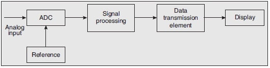
The above figure shows a block diagram of a digital voltmeter or Digital Voltmeter Systems (DVM). A digital instrument requires an analog to digital converter (ADC) to converter the analog value into a digital value. The ADC requires a reference. The reference is generated internally and reference generator circuitry depends on the type of ADC technique. The output of the ADC is applied to the signal processing unit. Then it is transmitted to the display. The data transmission elements may be latches, counter, etc. depending on the method used. The digital display shows the digital result of the measurement.
Advantages of Digital Voltmeter
Although there are several advantages of DVMs:
- Due to digital display, human errors like parallax are removed
- The accuracy is up to ± 0.005 % of the reading.
- The reading speed is high due to the digital display.
- Compatibility with other digital equipment for further processing and recording.
- Due to its small size, portable.
Types of Digital Voltmeter
Following are the different types of digital voltmeters:
- Ramp type DVM
- Dual-slope integrating type DVM.
- Successive-approximation DVM
- Potentiometer type DVM
Ramp-Type DVM
The block diagram of a ramp-type digital voltmeter is shown in the figure below. As seen from this diagram, it consists of a voltage-to-time conversion unit and a time measurement unit.

Operation of Ramp-Type Digital Voltmeter
The operating principle of the ramp type DVM is based on the measurement of the time taken by the DVM for a linear ramp voltage to rise from 0 V to the level of the input voltage or to decrease from the level of the input voltage to zero. This time period is measured with an electronic time-interval counter and the count is displayed as a number of digits on a digital display.

At the start of measurement, a ramp voltage is initiated. The ramp voltage can be negative or positive. The above figure shows a negative-going ramp, this ramp is continuously compared with the unknown input voltage. At the instant that the ramp voltage equals the unknown voltage to be
measured, a coincidence circuit or comparator generates a pulse to open the gate. The ramp voltage continues to decrease with time until it finally reaches 0 V. At this instant the ground comparator generates an output pulse to close the gate.
The time between opening and closing of the gate is Δt as shown in Fig. 6.19. During this time interval pulses from a clock pulse generator pass through the gate and are counted and displayed.
An oscillator generates clock pulses that are allowed to pass through the gate to a number of counting units which totalize the number of pulses passed through the gate.
The sampling rate multivibrator determines the rate at which the measurement cycles are initiated. The sample-rate circuit provides an initiating pulse for the ramp generator to start its next ramp voltage.
Advantages of Ramp-Type DVM
Following are the two main advantages of ramp-type digital voltmeter:
- The circuit is easy to design and low in cost.
- Output pulse can be transmitted over long distances.
Disadvantages of Ramp-Type DVM
Following are the three main disadvantages of ramp-type digital voltmeter:
- Single ramp requires excellent characteristics regarding linearity of ramp and time measurement.
- Large errors are possible when noise is superimposed on the input signal.
- Input filters are required for this type of converter.
Dual-Slope Integrating Type Digital Voltmeter
With the development and perfection of IC modules, the size and power requirement of DVMs have reduced to a level where they can compete with conventional analog instruments both in price and portability.
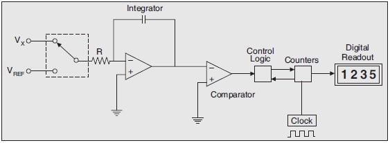
The block diagram of a DVM based on the dual-slope technique is shown in the figure below. The dual-slope analog-digital (A-D) converter consists of five basic blocks: an Op-Amp used as an integrator, a level comparator, a basic clock (for generating timing pulses), a set of decimal counters, and a block of logic circuitry.
Operation of Dual-Slope Integrating Type DVM
The operation of the dual-slope integrating type digital voltmeter may be explained as follows:
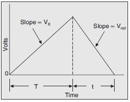
The unknown voltage Vx is applied through switch S to the integrator for a known period of time T as shown in the figure below. This period is determined by counting the clock frequency in decimal counters. During time period T, C is charged at a rate proportional to Vx.
At the end of time interval T, S is shifted to the reference voltage Vref of opposite polarity. The capacitor charge begins to decrease with time and
results in a downward linear ramp voltage. During the second period a known voltage (i.e. Vref is observed for an unknown time (t). This unknown time t is determined by counting timing pulses from the clock until the voltage across the capacitor reaches its basic reference value (reference may be ground or any other basic reference level).
Advantages
Following are the main advantages of dual-slope integrating type DVM.
- Excellent noise rejection as noise and superimposed ac are averaged out during the process of integration.
- The RC time constant does not affect the input voltage measurement.
- A sample and hold circuit is not necessary.
- The accuracy is high and can be readily varied according to the specific requirements.
Disadvantage
The speed of DVM is very slow, as compared to other DVMs.
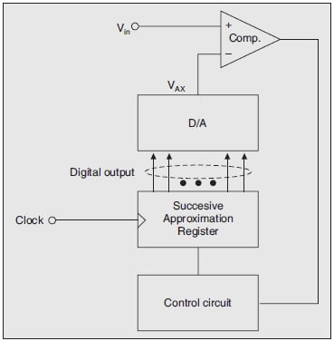
Successive-approximation Digital Voltmeter
The block diagram is shown in the figure below. The output of the DAC is compared with the unknown voltage by the comparator. The output of the comparator is applied to the control circuit. The control circuit generates the sequence of code that is applied to DAC. Conversion time is fixed (not dependent on the signal magnitude) and relatively fast.
Operation
The operation of successive approximation DVM may be explained as follows:
The operation is similar to the example of the determination of the weight of the object. The object is placed on one side of the balance and approximate weight on the other side of the balance to determine the weight of the unknown object.
If the weight placed is more than the unknown weight, the weight is removed and another weight of a smaller value is placed and again the measurement is performed. Now if it is found that the weight placed is less than that of the object, another weight of smaller value is added to
the weight already present, and the measurement is performed. If it is found to be greater than the unknown weight, the added weight is removed and another weight of a smaller value is added. By such a procedure of adding and removing the appropriate weight, the weight of the unknown
object is determined.
In successive approximation type DVM, the comparator compares the output of the digital to analog converter with the unknown voltage. The comparator provides logic high or low signals. The digital to analog converter successively generates the set of pattern signals. The procedure
continues till the output of the digital to analog converter becomes equal to the unknown voltage.
Advantages
Following are the main advantages of successive approximation type DVM:
- Very high speed of the order of 100 readings per second possible.
- Resolution up to 5 significant digits is possible.
- Accuracy is high.
Disadvantages
Following are the main disadvantages of successive approximation type DVM:
- The circuit is complex.
- Digital to Analog is required.
- Input impedance is variable.
- Noise can because error.
Related Posts: