Table of Contents
Oscilloscope Probes
Oscilloscope Probes are a conducting wire which is used to establish a connection between the circuit under test and the measuring instrument. While connecting the test circuit, the probe does not alter, load or disturbs the circuit and signal conditions to be analyzed.
Any signal going to the oscilloscope will first pass through the probe. Therefore bandwidth of probes combines with the bandwidth of CRO. The probe bandwidth must be higher than the oscilloscope bandwidth. The probe bandwidth is chosen to at least 10 times of CRO frequency.
The probe should have high impedance. The probe bandwidth should be as high as possible. It should be about 10 times the bandwidth of the oscilloscope. The ideal oscilloscope probes offer the following key attributes:
- Ease of connection
- Absolute signal fidelity
- Zero signal source loading
- Complete noise immunity
The general diagram of the oscilloscope probes is shown in the Figure below.
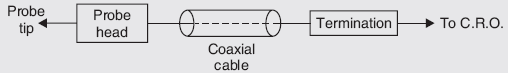
The probe tip is the signal sensing circuit. It may be passive or active. If it is passive, it consists of the resistors and capacitors. If it is active, it consists of active components like a FET source follower circuit.
The probe cable is a special coaxial type (with a resistive center conductor to damp out ringing), with quite-effective shielding. Its capacitance is greater than that of open-wire, and in some cases, such a probe is satisfactory.
The probes are of many types, they are given below:
- Direct probe
- Isolation Probe
- High impedance or 10: 1 Probe
- Active Probes
- Current Probe
- Differential Probes
Direct Probe 1:1

- These are the simplest type of probes.
- These probes terminate with banana tips or other types of tips.
- The tip of the probe has crocodile clips or other means of connecting the oscilloscope to the test circuit.
- The probes use shielded co-axial cable.
- This type of probe does not provide any improvement in the input impedance. They are called as “1X probes”.
- The input impedance of the vertical amplifier of a general-purpose CRO is 1 MΩ and input capacitance is 30 pF. When the direct probe is used, the input resistance remains constant at 1 MΩ. But the input capacitance of the oscilloscope gets added to the probe capacitance.
- The effect of shunt capacitance can be minimized by using a carbon resistance in series with the test leads. Such probes are called isolation probes.
Isolation Probe
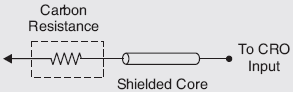
- The input capacitance of the oscilloscope and the stray capacitance of the test lead are very high. It causes the sensitive circuit to break into oscillation when CRO is connected.
- This effect can be prevented by an isolation probe. The isolation probe is made by placing a carbon resistor in series with a test lead.
- An isolation probe is employed to avoid the undesirable circuit loading effect of the shielded probe.
- This probe causes a slight change in the amplitude of the waveform and a slight change in the wave shape.
- To avoid this possibility, a high impedance compensated probe, called a low capacitance probe or a 10:1 probe is used.
High Impedance or 10: 1 Probe
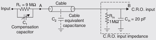
- This probe is also known as a passive voltage probe.
- The basic function of this probe is to increase the input impedance and reduce the effective input capacitance of an oscilloscope.
- This probe head uses a parallel resistor and capacitor combination.
- The resistance R1 is shunted by an adjustable capacitor C1. This capacitor is called a compensating capacitor.
- The resistor R1 and C1 are designed such that, input increases by factor 10 and input capacitance decreases by a factor of 10. Therefore this combination of R1 and C1 is called x10 probe.
- Let C2 be the probe cable equivalent capacitance. The input resistance and capacitance of CRO can be referred to as Rin and Cin. The typical values of Rin and Cin are 1 MW and 20 pF.
Active Probe
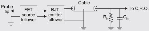
- The active probes are used for connecting fast-rising and high-frequency signals.
- These probes are very useful for small signal measurements as their attenuation factor is very small.
- The active probe consists of an active element like FET source follower circuit and BJT emitter follower circuit along with a co-axial cable termination.
- FET source follower provides high input impedance which reduces loading effect.
- Following the FET source, there is a BJT emitter follower. It drives the cable and provides impedance matching.
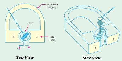
Current Probe

- CRO can be used to measure current if the current is converted to a voltage. It is done by the current probe.
- It uses the concept of the Hall Effect. According to Hall Effect, when a current flow in conductor or semiconductor which is perpendicular to the magnetic field, a potential difference appears between the opposite edges of conductor or semiconductor at right angles to the current and to the magnetic field.
- This probe provides a method of inductively coupling the signal to the CRO input.
- The direct electrical connection between the test circuit and CRO is not necessary.
- This probe can be clamped around a wire carrying an electrical current without any physical contact to the probe. Thus the magnitude of current with a frequency range from d.c to 50 MHz can be measured using this probe.
- The current sensor consists of two parts: A conventional transformer for transforming the alternating current to voltage, and a Hall Effect device for converting direct current to a voltage.
- A magnetic core with a removable piece is used as the coupling element for the current probe.
- The wire carrying the current to be measured is inserted in the center of the magnetic core and acts as a primary of a transformer.
- The core is the ferrite U shaped and work as secondary of the transformer. Because of the electromagnetic induction principle, whenever current flows through primary, the e.m.f gets induced in the secondary. This is fed to the CRO input via termination circuitry.
Differential Probes
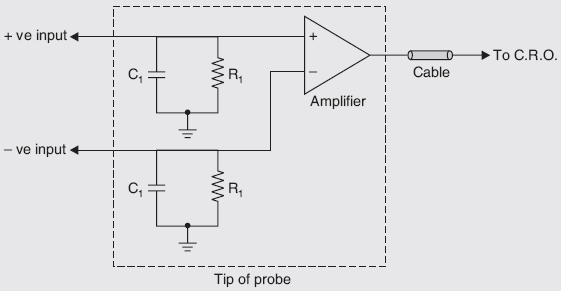
- They are an active probe.
- It has two inputs, positive and negative.
- It has a separate ground lead and it drives single terminated 50Ω cable to transmit its output to one oscilloscope channel.
- The output voltage signal is proportional to the difference between the voltages appearing to the input terminals. There is a restriction that the two input signals must be within a few volts from the ground so that signals can stay within the dynamic range of the probe.
- The output is proportional to the difference between the two inputs and hence the name, differential probe.
- The common-mode rejection ratio is best for DC and at low frequencies. But at high frequencies the rejection is poor.
- The capability of the differential probe is typically less than a few volts only.
- The peaks above certain amplitudes will be clipped in such probes. This probe is bulky, expensive, having less dynamic range and requires an external power supply.