Table of Contents
Optical Fiber Connector
Optical Fiber Connector is a mechanism or technique used to join an optical fiber to another fiber or to a fiber optic component.
A fiber-optic connector is a device which is used to efficiently couple and decouple two, or two groups of, fibers. The criteria for designing a connector are that it must
- allow for repeated connection and disconnection without problems of fiber alignment and/or damage to fiber ends.
- be insensitive to environmental factors such as moisture and dust, and capable of bearing load on the cable,
- have low insertion losses (which should be repeatable) and low cost.
Since it is difficult to optimize all three parameters simultaneously, the design of a connector is a compromise between ease and economy, on one hand, and the level of performance, on the other.
Characteristics of Optical Fiber Connector
- Low coupling loss.
- Inter-changeability – No variation in loss whenever a connector is applied to a fiber.
- Ease of assembly.
- Low environmental sensitivity.
- Low cost – The connector should be in expensive also the tooling required for fitting.
- Reliable operation.
- Ease of connection.
- Repeatability – Connection and reconnection many times without an increase in loss.
Types of Optical Fiber Connector
A number of fiber-optic connectors have been developed. These may be grouped in two categories, namely,
- Butt-jointed
- Expanded-beam connectors.
Butt-jointed Connectors
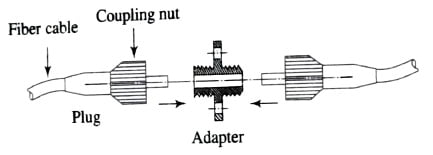
Butt-jointed connectors are based on the principle of aligning the two fiber ends and keeping them in close proximity (i.e., butted to each other). For this purpose, the plug-in-socket configuration shown in the figure below is normally employed.

The mechanical connection between the plug and the adapter on both ends is made with the help of either threaded nuts or bayonet locks. Some connectors employ standard BNC or SMA configurations. The design of connectors differs mainly in the technique of aligning fiber ends. The simplest connector design is shown in the figure below.

It consists of metal plugs (normally called ferrules), which are precision-drilled along the central axis. The prepared fiber ends (to be connected) are placed in these holes. They are then permanently bonded to the ferrules by an epoxy resin. A spring retains the ferrule in its position. The two opposite ferrules are aligned by a coaxial cylindrical alignment sleeve.
Another plug-adapter-plug design is shown in the figure below. Instead of metal ferrules, it employs ceramic capillary ferrules. Ceramic has better thermal, mechanical, and chemical resistance than metal or plastic.

Expanded-beam Connectors
An alternative design of connectors is based on expanded-beam coupling, illustrated in the figure below.

This technique uses two microlenses for collimating and refocusing light from one fiber end to another. As the beam diameter is expanded, the requirement of lateral alignment of the two plugs in an adapter becomes less critical as compared to butt-jointed connectors. Fresnel reflection losses may increase in this case but are normally reduced with the help of anti-reflection coating on the lenses.
Multifiber Connectors
In order to couple a number of fibers from two multifiber cables, multiple connectors are normally used. High-precision grooved silicon chips are employed to position fiber arrays. One chip can accommodate 12 fibers, and it is possible to stack many such chips. This structure is secured with the aid of spring clips and metal-backed chips as shown in the figure below.

Installing Fiber Connectors
The method of attaching fiber optic connectors to optical fibers various connector types. Following are the basic steps for installing fibers –
- Cut the cable one inch longer than the required finished length.
- Carefully strip the outer jacket of the fiber with ‘no nick’ fiber strippers. Cut the exposed strength members and remove fiber coating.
- Thoroughly clean the bared fiber with isopropyl alcohol poured onto a soft, lint-free cloth such as Kim vibes. Never clean the fiber with a dry tissue.
- The connector may be attached by applying epoxy or by crimping.
- Anchor the cable strength members to the corner body. This prevents direct stress on the fiber.
- Prepare the fiber face to achieve a good optical finish by cleaning and polishing the fiber end.
Connector Return Loss
At the connection point of the optical link, low reflectance levels are desired since the optical reflections can be a source of unwanted feedback into the laser cavity. Due to this unwanted feedback, the optical frequency response may degrade, also it generates internal noise within the source affecting overall system performance. The figure below shows this connection model.

The return loss for the index-matched gap region is given by,
R_{L}=-10log\left \{ 2R\left [ 1-\cos (\frac{4\pi n_{1}d}{\lambda }) \right ] \right \}Where, d is the separation between fiber end.
n1 is index-matching material.
R is reflectivity constant.
Related Posts: