Table of Contents
Raman fiber amplifier (RFA)
A Raman fiber amplifier (RFA) is based on an intrinsic non-linearity present in the form of a stimulated Raman scattering (SRS) mechanism. When a high-power optical signal (pump signal) propagates through the silica fibers, then SRS occurs.
How is SRS different from stimulated emission?
• In case of stimulated emission, an incident photon of the input optical signal stimulates emission of another identical photon without losing its energy.
• In the case of SRS, the incident photon of the pump optical signal gives up some part of its energy to create another photon of reduced energy at a lower frequency. This phenomenon is termed inelastic scattering. The remaining energy of the incident pump signal is absorbed by the medium in the form of optical phonons.
In a nutshell, Raman fiber amplifiers must be pumped optically in the optical silica-made fiber itself in order to provide optical gain. The figure below illustrates the use of an optical fiber as a distributed Raman fiber amplifier.
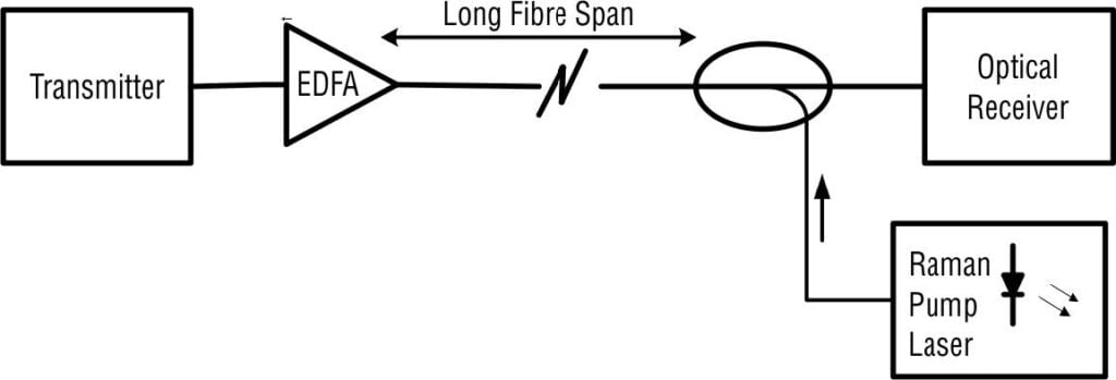
As shown, the pump signal from Raman pump laser diode at angular frequency ωp is injected into the transmitted optical signal propagating into the long fiber span at angular frequency ωs at a specific point through a fiber coupler. As these two optical signals co-propagate inside the fiber, the optical energy from Raman pump laser is transferred to the optical signal. It is important to note here that SRS Raman pumping takes place only in the backward direction (i.e., towards optical receiver side) over the fiber. Thus, the optical gain decreases in the direction of the transmitter, whereas it is maximum closer to the receiver end.
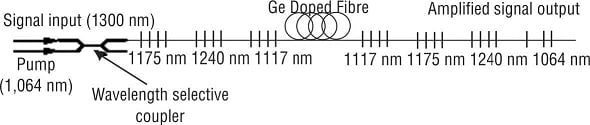
As seen, the optical signal input (at 1300 nm wavelength) and the optical pump signal (at 1064 nm wavelength) enter the Ge doped fiber together through a wavelength selective coupler. A high level (around 20%) of Ge dopant is used in silica fiber in order to increase the SRS effect. The pump signal at 1064 nm is shifted to higher wavelengths in stages and then pumps the 1300 nm input signal by the SRS mechanism. In this way, sufficient optical gain is obtained.
Performance Parameters of Raman fiber amplifier (RFA)
The gain of Raman fiber amplifier is given as
G_{R}=e^{\left (\frac{g_{R}P_{p}L_{eff}}{KA_{eff}} \right )}where gR is Raman power gain coefficient, Pp is optical pump power, L_{eff}=\frac{1-e^{-\alpha _{p}L}}{\alpha _{P_{2}}} is the effective fiber core length (αp being the fiber transmission loss at the pump wavelength and L being the actual fiber length), K is constant (=2 in single-mode fiber), and Aeff = πreff is the effective fiber core area (reff being the effective core radius).
Two figures below show Raman gain (GR) versus fiber length (L) plot for different values of pump power in Raman optical amplifiers.

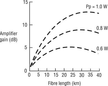
It is observed that Raman gain (GR) becomes larger as fiber length L increases up to around 50 km where it reaches an almost constant value. Higher value of GR can be achieved with low-loss fibers. Moreover, GR is increased as fiber core diameter is decreased. However, there is requirement of high optical pump signal power.
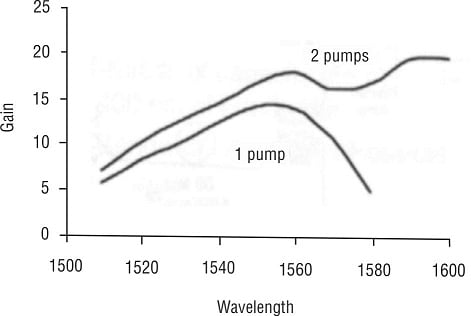
Wide bandwidth Raman optical amplifiers can be realized using multiple pumps. The figure below shows Raman optical gain versus wavelength characteristics with one pump and two pumps.
Advantages and Applications of RFAs
- Raman fiber amplifiers are mainly used as a preamplifier for improving receiver sensitivity as they can provide upto 20-dB gain for 1W of pump signal power.
- Due to their low noise figure (approximately 4 dB), they can be employed as optical preamplifier for high speed optical receivers.
- RFAs have broad bandwidth, so these are used for amplifying several channels simultaneously (WDM applications).
Drawbacks of RFAs
- High optical pump power is required.
- Rayleigh crosstalk may be present due to backscattering.
- Raman gain is sensitive to polarization of the input optical signal to some extent.