Table of Contents
Dispersion in Optical Fibers
Dispersion in Optical Fibers : Dispersion, also known as pulse spreading, means spreading out of an optical pulse of light energy in time as it propagates down a fiber. Dispersion occurs because of the difference in the propagation time taken by the light rays that traverse different propagation paths within the fiber. If the pulse spreading is sufficiently severe, one pulse may interfere with another.
Dispersion is another mechanism of signal loss in the optical fiber. In this, propagating pulse is broadened as it passes from Tx to Rx via optical fiber medium. It affects the rise time and fall time of propagating pulse due to birefringence, group velocity dispersion, and refractive index variation.
General Concept of Dispersion in Optical Fibers
Dispersion in a single-mode step-index fiber: The light rays propagating down a single-mode step-index fiber (assuming radial dimension of the fiber being sufficiently small) is depicted in figure below.

The following is observed:
- There is only a single transmission path that all rays must follow as they propagate through the fiber length.
- Each ray of light travels the same distance in a given period of time, and there is virtually no intermodal dispersion.
- However, a light pulse, although propagating as a fundamental mode, has a number of spectral components, and the group velocity of the fundamental mode varies with frequency, that results in broadening of the transmitted optical pulse.
- This phenomenon is known as intramodal, or group velocity dispersion (GVD).
Dispersion in a multimode step-index fiber: Let us try to understand the phenomenon of dispersion that occurs in a multimode step-index fiber. Consider three different light rays that propagate down a multimode step-index optical fiber as illustrated in figure below.
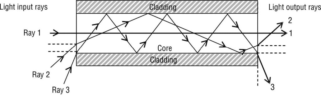
From the figure, the following is observed.
• The lowest-order propagation mode (i.e., light ray 1) travels in a path parallel to the central axis of the optical fiber.
• The middle-order propagation mode (i.e., light ray 2) bounces several times at the interface before traveling the length of the fiber.
• The highest-order propagation mode (i.e., light ray 3) makes many trips back and forth across the fiber as it propagates the entire length. It is quite evident that light ray 3 travels a considerably longer distance than ray 1 over the length of the cable.
Thus, if the three rays of light were emitted into the fiber at the same time, each ray would reach the far end at a different time. It implies that the propagated light energy would spread out with respect to time. As mentioned earlier, this is what is known as intermodal dispersion, or simply modal dispersion, that results in a stretched pulse that is also reduced in amplitude at the output of the fiber.
Dispersion in a multimode graded-index fiber: In order to understand the phenomenon of dispersion in a multimode graded-index fiber, let us consider three different light rays traveling through a multimode graded-index fiber, as depicted in figure below.
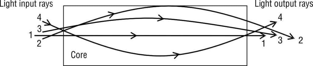
From the figure, the following is observed.
• Three rays are shown traveling in three different modes.
• Although the three rays travel different paths, they all take almost identical amount of time for propagating through the length of the optical fiber.
• This is due to the reason that the index of refraction decreases with radial distance from the center axis of the fiber core toward the cladding. We know that the velocity at which a ray travels is inversely proportional to the refractive index. So, the rays 2 and 3 travel farther away from the center of the cable, they propagate faster and reach the end almost at the same time as ray 1.
To summarize, in multimode fibers a light ray propagating straight down the central axis of the fiber core takes the least amount of time to travel the length of the optical fiber cable. A light ray that is incident at the intersection of the fiber and the cladding at the critical angle of incidence will undergo the largest number of total internal reflections. Consequently, it takes the longest time to traverse the length of the fiber cable.
Bandwidth × Length Product
For multimode propagation, dispersion is often expressed as a bandwidth-length product (B × L). Bandwidth-length product indicates what signal frequencies can be propagated through a given distance of fiber cable. Mathematically, (B × L) is expressed as the product of distance and bandwidth (sometimes called linewidth). Bandwidth-length products are often expressed in MHz-km units. As the length of an optical fiber cable increases, the transmission bandwidth (and thus the data rate) decreases in the same proportion.
The effects of modal dispersion increase with the length of the optical fiber cable because the difference in the velocity of two optical signals propagating down the fiber length produces a difference in the time required to reach the other end of the fiber. In fact, this time difference is directly proportional to the length of the fiber. The greater the bandwidth of the transmitted optical signal, the greater will be the effect of a given amount of modal dispersion. Practically, multimode step-index or graded-index fibers are rated in accordance with the product of transmission bandwidth and fiber length.
Pulse Spread and Maximum Data Rate
Definition of pulse-spreading constant: It is defined as the absolute time difference between the fastest and slowest light rays propagating through an optical fiber cable of unit length. It is also known as pulse-stretching constant. The unit of pulse-spreading constant is nanoseconds per kilometer (ns/km).
We are now interested to determine total pulse spread (ΔT). It can be easily derived from the basic definition of pulse-spreading constant. It is given as the product of pulse-spreading constant and the total fiber length (L). That is,
\Delta T_{(ns)}=\Delta t_{(ns/km)}\times \Delta L_{(km)}Types of Dispersion in Optical Fibers
Signal dispersion in optical fibers can be broadly classified in three main categories:
Chromatic or Intramodal Dispersion
This type of dispersion results from the finite spectral linewidth of the optical source. Propagation delay differences between the different spectral components of the transmitted light signal causes broadening of each transmitted mode and hence collectively known as intramodal dispersion. It may occur in all types of optical fibers (single-mode as well as multimode, step-index as well as graded-index). It is caused by the dispersive properties of the fiber material (material dispersion) and also guidance effects within the fiber structure (waveguide dispersion).
Intermodal Dispersion or Mode Dispersion
The main reason for intermodal dispersion, also known as mode dispersion, is that the difference in propagation delay between various propagation modes within a multimode fiber (hence, it is not applicable for single mode fiber). Different modes of a transmitted light pulse travel at different group velocities. Different transmission times between the fastest and slowest modes of propagation yields in broadening of transmitted optical pulse at the output of the fiber cable.
Polarization Mode Dispersion
Due to variations in the fiber core diameter in a practical single mode fiber, two orthogonal, linearly polarized modes are supported that are degenerate. The variations in the fiber core diameter may be due to the presence of non-uniform stress, bends, stress, etc. along the length of the fiber. As discussed earlier, propagation times are different because of difference in the group velocities among light rays, which give rise to pulse broadening or pulse dispersion.
Other Types of Dispersion in Optical Fibers
- Material dispersion as a function of wavelength
- Waveguide dispersion or modal dispersion
- Polarization mode dispersion
- Chromatic dispersion
Material Dispersion
This phenomenon is observed due to variation of core refractive index [n(λ)] as a function of optical wavelength propagating in the fiber. Different modes travel in fiber with different group velocity (Vg) where Vg is dependent on refractive index [n(λ)]. The source used in Tx has spectral width and hence, various spectral components of a given mode will travel at different velocities depending on the wavelength (λ).
The propagation constant (β) of propagating wave is
\beta =\frac{2\Pi n(\lambda )}{\lambda }Waveguide Dispersion
In the optical waveguide, various modes are travelling together. Some rays are travelling along the axis in the fiber and other rays travel at different angles with respect to axis. The critical angle ray is extreme ray travelling in the fiber as shown below. They have different travel times over a fiber length L as some rays are following zig-zag path. Hence, different rays in a multimode fiber have different transmission time. The outer extreme ray takes maximum travel time (Tmax) whereas the ray passing through axis takes minimum time (Tmin). The time difference in the propogation over a length L is responsible for waveguide or model dispersion. This is negligible in Single Mode fiber but significant in Multi Mode fiber.

Polarization Mode Dispersion (PMD)
Definition: Polarization mode dispersion (PMD) is defined as the difference in the propagation times (that is, pulse broadening) between two orthogonally polarized components of the light pulse in a single-mode fiber.
The propagation of light in single mode cylindrical fiber gives two nearly degenerate modes with orthogonal polarizations. These are bimodal HE_{11}^{x} and HE_{11}^{y} modes. Fiber behaves like birefringent medium due to difference in the effective refractive indices (ηeff) and hence, phase velocities for these two orthogonally polarized modes are different. The modes have different propagation constant βx and βy. The birefringence (BF) in z-direction is
B_{F}=\frac{\left (\beta _{x}-\beta _{y} \right )}{\left ( 2\Pi /\lambda \right )}where λ is optical wavelength over the length of fiber (L).
