Table of Contents
Multiplexing
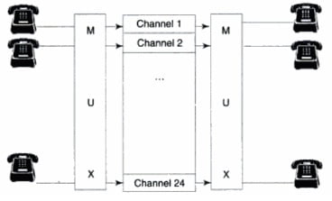
Multiplexing divides the physical line or a medium into logical segments called channels. In multiplexing, different channels carry data simultaneously over the same physical medium. Hardware equipment called multiplexer (mux) combine (or multiplexes) the inputs from different sources, and load them on different channels of a medium. The combined data traverses over the medium simultaneously. At the destination, a demultiplexer (demux) separates (or demultiplexes) the signals and sends them to their different destinations. This is depicted shown below. This is obviously cheaper than having three separate lines.

Thus, the mux is responsible for both multiplexing and demultiplexing. Therefore, it has to be present at both the ends of a medium. Multiplexing allows us to add new channels in the existing telephone line without having to install a new line. However, as the total capacity of the medium is limited, the capacity of each channel reduces when we increase the number of channels.
Types of Multiplexing
There are basically two ways in which multiplexing / demultiplexing can be achieved. They are
- Frequency Division Multiplexing (FDM)
- Time Division Multiplexing (TDM).
Frequency Division Multiplexing (FDM)
Introduction to FDM
Frequency Division Multiplexing (FDM) is a common technique used in public telephones and in the cable TV system, where a single cable carries multiple video signals from different channels or stations to your TV set. With the remote control, we essentially activate the electronics in the television to select a specific frequency band or a channel. This is how we see a specific program on the TV. The signals from other programs also actually traverse to your TV set on the same cable, but they lie idle at your TV set for you to choose from.
In FDM, the medium is divided into a number of channels, each with a frequency bandwidth, and therefore, a data rate. Though the composite signal ultimately carried by the medium is analog, the input signals can be analog or digital. If the input signals are analog, only multiplexers at both ends are sufficient as shown in the figure below. If the input signals are digital. such as from computers, they need to be passed through modems and multiplexers as shown in the figure below. Modems convert the digital signals into analog ones and then at the other end. convert them back into digital signals.
Frequency Division Multiplexing
FDM is very important in the context of the analog telephone system. In the analog telephone system. voice signals are carried over twisted copper wire pairs as analog signals from your home to the nearest exchange called the last mile. There is no conversion from analog signals to their digital equivalents at this stage of the transmission.


As we know, the frequencies of the human voice that are carried by the telephone system are in the range of 0 to 4000 Hz (4 kHz). Therefore, to carry a single voice conversation over the telephone, a bandwidth of 4 kHz is necessary and sufficient. However, the capacity of the medium such as a twisted wire pair or coaxial cable is far higher. That is where FDM comes in handy by enabling multiple conversations to take place over a single wire or cable.
As we know, this is useful in sending signals between exchanges or from local exchange to a higher level exchange. At an exchange, signals from multiple sources can be combined or multiplexed and then sent to a higher or different exchange. At the other end, they are demultiplexed and sent to the appropriate destinations. In the local loop. i.e. between the user and the local exchange, there is only one user and therefore, multiplexing is not possible.
Analog Telephone System

- At the first level, twelve voice channels, each having a bandwidth of 4 kHz, are multiplexed to form a Group. This group has a bandwidth of 48 kHz. A question arises at this stage: between any two channels, should some unused empty portion (called a guard band) be provided so that the signals of the two channels do not mingle with each other, causing mixing of signals and, therefore, loss of information? The answer is no. As we have discussed previously, the unused frequency bands of 0-300 Hz and 3300-4000 Hz themselves act as guard bands, and the 300-3300 Hz portion is used for voice traffic.
- At the next level, five such Groups are multiplexed to form a Supergroup. Thus, the bandwidth of a Supergroup is 5 x 48 kHz = 240 kHz. In other words, a Supergroup can carry sixty voice signals. each of bandwidth of 4 kHz.
- At the third level, ten Supergroups are multiplexed onto a channel of still higher bandwidth, called Mastergroup. Thus, the bandwidth of a Mastergroup channel should be 10 x 240 kHz = 2.4 MHz, but is normally kept at 2.52 MHz. Thus, a Master group can carry 600 voice signals, each of bandwidth of 4 kHz.
- At the last level, six Mastergroup channels are combined to form a Jumbogroup. The bandwidth of a Jumbogroup should be 6 x 2.52 MHz = 15.12 MHz, but is usually kept at 16.984 MHz. This means that a Jumbogroup can carry 3600 voice conversations.
Time Division Multiplexing (TDM)
Time Division Multiplexing (TDM) is a technique used for digital transmission only. In this case, we do not divide the frequency bandwidth of a medium into a number of channels. We divide the transmission time into a number of time slices. We then allocate each time slice to different source nodes, each of which wants to send some data. A node could mean a computer, a terminal or any device. During the time slice that a source node is sending some data, the entire bandwidth belongs to that source node. We know that the data rate in a medium is proportional to its bandwidth. Hence, the source node. which is sending some data during that time slice, can send the data at the high rate.
The time slice allocated to each source would be different because each node may want different amounts of data to be transmitted. This philosophy may require a large amount of buffer at each source node to hold the data when some other source node is transmitting. In addition, this method can be very unfair to a few source nodes as it may involve long waits or indefinite postponement if one of the source nodes grabs the medium for a very long time. This is the reason why the time span is divided into equal time slices. There are two ways of allocating the time slices to various source nodes. They are given below:
- Synchronous TDM, also known as TDM
- Statistical TDM
Synchronous TDM or TDM
In the technique called synchronous TDM, also referred to as TDM. In this technique, the time slice is allocated to a source node regardless of whether it wants to send some data or not. This is a fairly simple mechanism to identify, at a destination node, which data originated from which source node, since every source node has a fixed time slot. Therefore, the position of the data within the data frame specifies its origin. However, it can be a very wasteful scheme, because the time slot is allotted to a source node even if it has nothing to send.

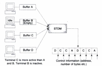
A small buffer memory is associated with every source node. At any time, not all nodes may want to send some data. Regardless of this, the timing device in the multiplexer allocates some time for each node to transmit the data from its buffer, and then repeats this cycle e.g. A-B-C-D-A-B-C-D etc. as shown in the figure. By the time its turn comes next, if a node wants to transmit any data, it will have moved a small chunk of data to its buffer. If there is no data to be transmitted, the buffer will be empty. but still the turn of the node will come, as depicted in Fig. 4.21. (Refer to node B). Notice that there is no addressing scheme here to identify the source of the data. The position of the data in the composite message determines the source address.
Statistical Time Division Multiplexing (STDM)
Statistical Time Division Multiplexing (STDM) is a variation of the TDM technique. This technique is more intelligent. It monitors which machine or terminal is sending data more frequently and in greater quantity, and allocates the time slices more often to those nodes. Relatively inactive computers/ terminals get the time slice less often, while a completely idle computer/terminal may not get any time slice at all. Essentially statistical data is kept about the activity of various source nodes and hence the name. This is shown in the figure below. In the figure, node B does not send any data at all. while node C is more active and hence is polled more frequently.

This allows more number of computers/terminals to be connected to the line. For instance, on a 9.6 Kbps line, you can connect only eight terminals sending data at the rate of 1200 Kbps or 1.2 Kbps using ordinary TDM. With STDM, you can connect more number terminals, because, at a given time, not all terminals are active and want to send data. This technique will work so long as the number of terminals wanting to send the data at any moment does not exceed eight.
It should be obvious that the position of the data in the total data frame sent does not determine its address. In TDM, this was the case. In STDM, a time slot could be allotted to any of the nodes depending upon its past activity, and the pending current requests. Therefore, in STDM, along with the chunk of the data, some control information is sent in the data frame, which contains the addresses of both the sender and the receiver as well as the number of bytes sent, etc.
At the destination, another stat mux (a statistical multiplexer is called stat mux) captures the frame, separates out the data chunks and the receiver’s address, and sends the data to the appropriate destination. Here, the sender’s address tells the receiver (destination) from whom the data has been received. This is unlike TDM where the sender was defined by the time slot and therefore, it was not necessary to transmit the sender’s address explicitly.
Related Post:
Network Topology and its Types


