Table of Contents
Circuit Switching
In-circuit switching, two communicating stations are connected by a dedicated communication path which consists of intermediate nodes in the network and the links that connect these nodes. In-circuit switching, an electrical dedicated path is established between the source and the destination before any data transfer takes place. The electrical path may be realized by physical wires or radio or satellite links.
What is significant about circuit switching is that the communication path remains intact for the duration of the connection, engaging the nodes and the links involved in the path for the period. However, these nodes and links are typically capable of supporting many channels, so only a portion of their capacity is taken away by the circuit.
Circuit switching takes place at the physical layer. Data transmission using a PSTN connection is a typical example of a circuit-switched data transfer.

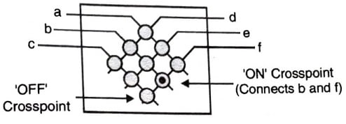
The above figure shows a simple circuit switch which consists of a 3×3 matrix, capable of connecting any of its inlets (a, b, and c) to any of its outlets (d, e, and f).
Each cross point appears as a circle. A hollow circle means that the cross point is off i.e., the two crossing wires are not connected. A solid circle means that the cross pturit is on i.e., the crossing wires are connected. The switch can support up to three simultaneous but independent connections. Although, we have used an equal number of inlets and outlets here, in general. this need not be the case. Switches may also have more inlets than outlets, or more outlets than inlets. Each link is normally divided into n-channels by using FDM (Frequency Division Multiplexing) and TDM (Time Division Multiplexing).
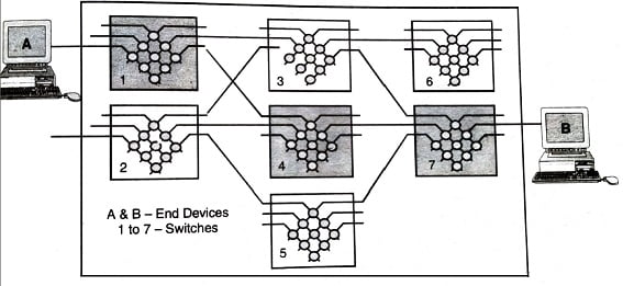
The above figure shows a simple circuit-switched network built using the circuit switch. When the two hosts shown in the figure initiate a connection, the network determines a path through the intermediate switches and establishes a circuit which is maintained for the duration of the connection. When the hosts disconnect, the network releases the circuit.
Different phases or Circuit Switching
A circuit switched network has three phases which are as follows:
- Setup phase
- Data transfer phase
- Tear down phase
Setup/Connection Phase
Network use is initiated by the connection phase, during which a circuit is set up between source and destination and terminated by a disconnect phase. These phases, with associated timings, are illustrated in the figure below.
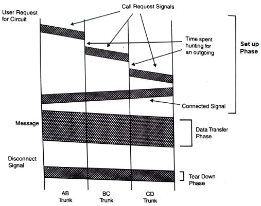
Atter a user request a circuit, the desired destination address must be communicated to the local switching node (B). In a telephone network, this is achived by dialing a number.
Node B receives the connection request and identifies a path to the destination (D) via an intermediate node (C). This is followed by a circuit connection phase handled by the swaching nodes and initiated by allocating a free circuit to C (link BC), followed by transmission of a call request signal from node B to node C. In turn, node C allocates a link (CD) and request is the passed to node D after a similar delay.
Data Transfer Phase
The circuit is then established and may be used. While it is available for use, resources and capacity on the links between the equipment are dedicated to the use of the circuit.
After completion of the connection, a signal confirming circuit establishment is returned. This flows directly to node A with no search delays since the circuit has been established. Transfer of data in the message then begins.
Tear Down Phase
After data transfer, the circuit is disconnected. A simple disconnect phase is included after the end of the data transmission.
Propagation Time in Circuit Switched Network
The propagation time is dependent upon the medium of transmission and the electrical distance between sources to the destination. Free space propagation speed is 3 x 10⁸ m/s as the speed of the electromagnetic wave and through coaxial cable, its speed is 200 m/µs.
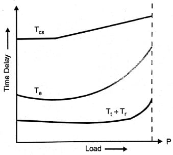
The above figure shows the variations of delay components in circuit switching.
T_{CS}=T_{e}+T_{t}+T_{r}Where, Tcs= Total circuit switching delay
- Te = Connection establishment time
- Tt = Data transmission time
- Tr = Connection release time Data transmission time
Te is a set up time and depends upon the number of switches.
Where, N = Number of switching nodes, Tm = Average route selection time for each node
T_{t}=\left ( \frac{M}{R} \right )
Tt is a data transmission time and depends upon the data rate and size of message.
M = Message length in bits
R = Data rate in bps
T_{r}=(NT_{n})Where Tn = Time needs to make housekeeping entries by each node.
Tr is connection releasing time and depends upon number of switching nodes. On receiving disconnection request signal from each node, the circuit performs certain housekeeping operations, such as making entries in the routing table.
Then the total circuit switching delay may be further written as
T_{CS}=(N-1)T_{m}+(\frac{M}{R})+(NT_{n})Advantages/Disadvantages
- Circuit switching relies on dedicated equipment especially built for the purpose, and is the dominant form of switching in telephone networks. Its main advantage lies in its predictable behavior: because it uses a dedicated circuit, it can offer a constant throughput with no noticeable delay in transfer of data. This property is important in telephone networks where even a short delay in voice traffic can have disruptive effects.
- Delays for setting up a circuit connection can be high, especially if ordinary telephone equipment is used. Call setup time with conventional equipment is typically on the order of 5 to 25s after completion of dialing. New fast circuit switching techniques can in theory reduce delays to approximately 140ms. Trade-offs between circuit switching and other types of switching depend on switching times.
- Circuit switching main disadvantage is its inflexibility in dealing with computer Oriented data. A circuit uses a fixed amount of bandwidth, regardless of whether it is used or not. In case of voice traffic. the bandwidth is usually well used because most of the time one of the two parties in a telephone conversation is speaking. However, computers behave differently; they tend to go through long silent periods followed by a sudden burst of data transfer. This leads to significant underutilization of circuit bandwidth.
- Another disadvantage of circuit switching is that the network is only capable of supporting a limited number of simultaneous circuits. When this limit is reached, the network blocks further attempts for connection until some of the existing circuits are released.
- There is no error control facilities used in circuit switched network.
- The speed of the operation of the circuit is limited by slowest link in circuit.
- Circuit switched treats all the transmission equally There is problem to prioritize messages and select transmission paths.
Efficiency of circuit switching
The circuit switched networks are not as efficient as the other two types of networks because the resources are allocated during the entire duration of connection. Now these resources are not available to other users. Normally, in telephone network, users terminate the communication when not in use whereas in computer networks, a computer can be connected to another computer even if there is no activity for a long period.
In-circuit switching, an electrical dedicated path is established between the source and the destination before any data transfer takes place.