Table of Contents
Packet Switching
Packet Switching is the main alternative of circuit switching. Packet switching was designed to provide a more efficient facility for bursty data traffic. In packet switching system statistical multiplexing is used in which communication from multiple sources is done by using shared media. In packet switching each message is divided into blocks of data that are known as packets. The maximum packet size is defined in each packet switching technology. Each packet contains some portion of the user data plus control info needed for the proper functioning of the network. Each packet has a ‘header address’ which contains the receiver address, so it knows where to go.
The header address also describes the sequence for reassembly at the receiver so that the packets can be arranged in the correct order. One packet also contains details of how many packets should be arriving so that the receiver knows if one packet has failed to turn up. These packets are sent out from the computer and they travel around the network seeking out the most efficient route to travel as circuits become available which may not be necessarily the shortest route. Each packet may go a different route from the others. If a packet fails to arrive, the receiver sends a message back to the transmitter, asking for the missing packet to be resent.
In packet switching there is arbitrary communication. It allows a sender to communicate with one recipient or multiple recipients and similarly any recipient can receive messages from one sender or multiple senders. Packet switching is asynchronous and communication can occur at any time.A sender can have arbitrarily long delay between successive packets.
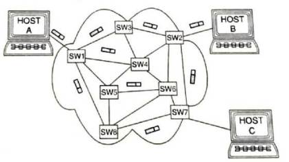
In packet switching, a sender does not need to perform initialization before communicating. It does not need to notify the underlying system when communication terminates and can send a packet to any destination at any time. A data switching Exchange (DSE) is used, which is a network node interlinking three or more paths. The packets are sent towards the destination irrespective of each other.
Each packet finds its own route to the destination using the information it carries, such as the source and destination IP addresses. There is no predetermined path and the decision as to which node to hop to in the next step is taken only when a node is reached. The node computers do not store data. As soon as a receiving node acknowledges to the transmitting node that it has correctly received the transmitted data, by doing an error check, the transmitting node deletes the data. In packet switching, multiplexing occurs among packets rather than among bits or bytes. Once a sender gains access to the underlying channel, the sender transmits an entire packet and then other senders can transmit a packet using the same communication channel. Examples of packet switching networks are X.25, Frame Relay, ATM, and IP.
Advantages of packet switching
- More efficient due to flexibility in routing the smaller packets over shared links.
- Packet switching networks are often cheaper to build as less equipment is needed that arises from sharing.
- Another benefit of packet switching is, devices of different speed can communicate.
- Destination information is contained in each packet, so numerous messages can be sent very quickly to many different destination.
- Packet switching uses error detection and correction methods.
- Not affected by line failure (redirects signal).
- During a crisis or disaster, when the public telephone network might stop working, e-mails and texts can still be sent via packet switching.
Disadvantages of packet switching
- Longer delays in receiving messages due to the time required to package and route packets.
- Under heavy load, there can be a delay.
- Data packets can get lost or become corrupted.
- Not so good for some types of data streams but additional data compression and quality of service (QoS) technology can be used to achieve the required performance levels.
- Potential for network security risks due to the use of shared physical links.
Modes of Packet Switching
There are two modes of packet switching-
- Datagram switching is also known as connectionless packet switching.
- Virtual circuit switching also is known as connection-oriented packet switching.
Datagram Switching
The most common packet switching is datagram switching or connection-less packet switching. In datagram switching, a packet now called a datagram is treated as a separate entity. It is routed independently through the network. The header is included in the packet with the full information about the intended receiver and sometimes the sequence number of the packet. The nodes examine the header of a packet and select an appropriate link to the intermediate node which is nearer to the destination. Here, datagrams do not follow a pre-established route. The intermediate nodes called routers do not require prior knowledge of the routes that will be used. The below figure shows the transmission of packets from workstation A to workstation B using datagram switching.
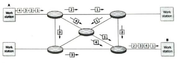
The individual packets may follow different paths between the source and the destination. As a result, the packets may arrive at the destination out of order. When this occurs, the packets will have to be reassembled to form the original message.
This is analogous to sending a message as a series of postcards through the postal system. Each card is independently sent to the final destination. The receiver must collect all the postcards and sort them into the original order to receive the whole message.
Since each packet is switched independently, there is no need for connection setup and no need to dedicate bandwidth in the form of a circuit. In a datagram network delivery is not guaranteed and some additional functions such as end-to-end error and sequence control are required to provide reliable communication.
The most common datagram network is the Internet, which uses the IP network protocol. Applications that do not require more than a best-effort service can be supported by direct use of packets in a datagram network, using the User Datagram Protocol (UDP) transport protocol. A UDP protocol is shown in the figure below.
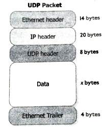
Applications using UDP include intemet voice and video communications and notifying messages to alert a user that she/he has received new e-mail are using UDP. Applications like e-mail, web browsing and file upload and download need reliable communications, such as guaranteed delivery, error control and sequence control. This reliability ensures that all the data is received Data I x bytes in the correct order without errors. It is provided by a protocol such as the Transmission Control Protocol (TCP) or the File Transfer Protocol (FTP) which uses UDP.
There are three primary types of datagram packet switches :
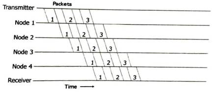
1. Store and forward. Store and forward packet buffers the data until the entire packet is received and checked for errors. This prevents the corrupted packet from propagating throughout the network at the cost of an increase in switching delay.
2. Fragment free. It filters out most error packets but doesn’t necessarily prevent the propagation of errors throughout the network. It offers faster switching speeds and lower delay than store-and-forward mode.
3. Cut through. Cut through packet switches packets at the highest throughput, offering the least forwarding delay but it does not filter errors.
Virtual circuit switching
Virtual circuit switching is also known as connection-oriented packet switching. In this methodology, the initial setup phase is used to set up a fixed path between the source and the final destination through which all the packets will be routed during a session between the end nodes. This path is called a virtual circuit because to the user, the connection appears to be a dedicated physical circuit. However, other communications may also be sharing the parts of the same path.

Before the data transfer begins, the source and destination identify a suitable path for the virtual circuit. At each intermediate node an entry is made in their routing table to indicate the route for the connection that has been set up for the call. Additional parameters, such as the maximum packet size, are also exchanged between the source and the destination during call set up.
Packets can then use short headers since only identification of the virtual circuit rather than a complete destination address is needed. The intermediate nodes process each packet according to the information which was stored in the node when the connection was established. The virtual circuit is cleared after the data transfer is completed. The most common form of virtual circuit network was ATM, Frame Relay, and X.25, which for a while were commonly used for public packet data networks.
Advantages of virtual circuit switching
- Packets are delivered in order, since they all take the same route.
- Shorter headers are required since there is no need for each packet to contain the full address.
- Faster because no routing is done once a call is established.
- The connection is more reliable since resources are set up in advance that even during times of congestion, provided that a call has been set up, the subsequent packets should get through set up in advance.
Disadvantages of a virtual circuit-switched network
- The switching equipment needs to be more powerful since each switch needs to store details of all the calls that are passing through it.
- When a failure occurs, all virtual circuits must be set up again.