Table of Contents
Finite State Machine ( FSM )
A Finite State Machine (FSM) is a type of sequential circuit that is designed to sequence through specific patterns of finite states in a predetermined sequential manner. Every FSM basically consists of three parts :
Sequential Current State Register
- The register which is a set of n-bit flip-flops clocked by a single clock signal is used to hold the state vector (current state) of the FSM.
- A state vector with a length of n-bit has 2n possible binary patterns, known as state encoding.
- Often, all 2n patterns are not required, so the unused ones should be designed not to occur during normal operation.
- An FSM with m-states requires atleast log 2(m) state vector flip-flops.

Combinational Next State Logic
- An FSM can only be in one state at any given time, and each active transition of the clock causes it to change from its current state to the next state, as defined by the next state logic.
- The next state is a function of FSM’s inputs and its current state.
Combinational Output Logic
- Outputs are a function of the current stale and possibly FSM’s primary inputs.
- Often in a Moore FSM, you may want to derive outputs from the next state instead of the current state, outputs are registered for faster clock-to-out timings.
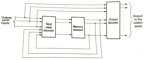
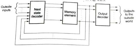
- The function of the combinational labeled next state decoder is to decode the inputs from the outside world and present state of the machine and to generate as its output, a code called the next state code.
- This next state code will become the present state when the memory loads and stores it. This process is defined as s STATE CHANGE or a CHANGE OF STATE.
- State change is continuous with each new state and present input condition being decoded to form the new state code.
- Thus each new succeeding state is a function of the present inputs and the past history of these inputs.
- The combinational logic block of the above figure shown labeled the output to world code converter has the basic function of decoding the present state of the machine and present input conditions for the purpose of generating the desired control outputs to the outside world.
Classification of Finite State Machine
All the models of FSM are derived from the general basic model of FSM shown in the above figure.
There are three classes for FSM. They are the class A, B and C.
Class A machine
- The class A machine is defined as a Mealy machine.
- The basic difference of the Mealy machine is that the outputs to the outside world are a function of two sets of variables :
- Present input conditions
- Present state of machine
Class B and C machine
- Class B and C machines are defined as Moore machine, another pioneer in sequential circuits.
- The basic difference of a Moore machine is that its output is strictly a function of the state machine.
- The block diagram of class B machine is shown in the figure below
- Both the Mealy and Moore machines are widely used and it is possible to derive machines which are mixtures of both.
- Class C machine, which is basically a Moore machine without an output decoder is shown figure below.

- The Class A, B, and C machines are equally applicable for both asynchronous as well as synchronous circuits and the minimum number of inputs to any of these machines is ONE. For a synchronous machine, this one input must be the system clock.
Moore Finite State Machine
• A Moore machine is defined as a sequential network whose output is a function of the present state only.
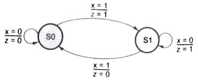
• State diagram of Moore machine has the output associated with the state, as shown in the following example :

- Moore state machine output is shown below the state value, as output remains the same as long as the state machine remains in that state.
- In the Moore machine, every combination must be represented with a different internal state.
- Moore machine is faster because the outputs are calculated from the current state which was itself calculated during the previous clock cycle. Thus the outputs are ready, very close to the current clock cycle.
Mealy Finite State Machine
A Mealy machine is defined as a sequental circuit whose output is a function of both the present state and external input to the circuit.

- The state diagram of a Mealy machine has output associated with the transition between states as shown in the state diagram in the above figure.
- Outputs are shown on transitions because they are determined in the same way as in the next state.
- In the Mealy machine, it is possible to represent both combinations using the same state and compute a single bit directly from the inputs. Hence, there are fewer states.
- In the Mealy machine, outputs are computed from the present state and current inputs and will not be ready for some time after the start of the clock cycle.
Finite State Machine in VHDL
- VHDL does not contain any formal format for finite state machines definition.
- Hence, in order to recognize a section of the VHDL model as a state machine, a set of coding guidelines must be followed. These guidelines do not, however, limit the user to one particular format of a state machine.
- When a state machine is to be described it contains the following specifications :
- A state variable, which specifies the state of the machine.
- A clock.
- Specification of state transitions.
- Specification of outputs.
- A reset condition; synchronous or asynchronous.
- Clock and reset can be specified in a PROCESS or BLOCK statement, but transition must be specified in a PROCESS statement.
- Output can be specified using any concurrent statement. All the state machine elements can be specified in a single process.
- The state variable is used to maintain the state of the circuit. Using the clocked process, its value is explicitly latched. When the clock edge occurs, the value of the next state is loaded into the registers.
- If the number of states is not correctly accounted for by all possible bit patterns in the state variable, regardless of the encoding method, “extra” states need to be addressed.
- If the user has described 4 states, instate machine, and choose to use a one-shot encoding scheme, the state variable will be four bits wide. The state variable has 16 possible bit patterns even though only four are used.
- In such a case, the VHDL description must be written to ensure that all potential cases are covered. Thus, when defining state transitions, use when others clause when using a CASE statement which defines the state transitions.
FSM Encoding
The four important FSM encoding styles are listed and explained in brief below :
- Binary encoding: Will generate state machines with the fewest possible flip-flops. Binary state machines are useful in critical design areas when timing is not a concern.
- Gray encoding: Will generate state machines where only one flip-flop changes during every transition. Gray encoded state machines tend to be glitchless.
- Random: These State machines are generated using random state encoding. Random state machine encoding should only be used when all other implementations are not achieving the desired results. It is like a shot in the dark and not a recommended style of FSM.
- One hot: The one-hot encoding will generate state machines containing one flip-flop for every state.
One hot state machine provides the best performance and shortest clock to output delays. The implementations of one hot machine are larger than binary but are the preferred choice for Xilinx FPGA architectures. This is because these devices are rich in flip-flops.
Applications of FSM
State machines are mainly used for system control applications. All the important applications are described below :
- In Digital Signal Processing applications (DSP), as a sequencer state machines offer speed and sufficient functionality without the need of complex microprocessors.
- For simple algorithms, such as those involved in performing Fast Fourier Transform (FFT), a state machine can control a set of vectors that are multiplied and added in the process.
- For complex DSP applications, a programmable DSP is a better solution. But programmable DSP is not as fast as the dedicated hardware approach.
- If the video controller is considered, it generates addresses for scanning purposes, using counters with sequences and lengths.
- There is an advantage apart from the economy part. A count can be set or initiated, then left to take care of itself, freeing the microprocessor for other operations.
- In peripheral control, the simple state machine approach can be efficient. If run-length-limited code is considered, both encoding and decoding can be translated into state machines, which examine the serial data stream, as it is read and generate the output data.
- Industrial control and robotics offer further areas where simple control functions are required.
- Data encryption and decryption present similar problems to those encountered in encoding and decoding. A programmable state machine device with a security bit is ideal for this because memory is internally programmed and cannot be accessed by someone tampering with the system.
Advantages of FSM
- FSMs are simple which make it easy for inexperienced developers to implement with little knowledge.
- Due to simplicity, FSMs are quick to design, quick to implement and hence quick in execution.
- Predictability (in case of deterministic FSMs), gives a set of inputs and known current state, state transition can be predicted, allowing easy testing.
- Due to their simplicity and FSM is an old knowledge representation and system modeling technique and its been around for long time, as such it is well proven even for artificial intelligence technique.
- Easy to transfer from abstract representation to a coded implementation.
- FSMs are relatively flexible. There are a number of ways to implement a FSM based system interms of topology and it is easy to incorporate many other techniques.
- Easy determination of reachability of a state, when represented in an abstract form. Wheather a state is achievable from another state and what is required to achieve the state is calculated.
- Low processor overhead; well suited to domains where execution time is shared between modules or subsystems.
Disadvantages of FSM
- The predictable nature of deterministic FSMs is not required in some domains.
- Conditions for state transitions are rigid, that is they are fixed, not flexible.
- Larger systems implemented using an FSM can be difficult to manage and maintain without a well throughout the design.
- Not suited to all problem domains, it should only be used when a system behavior can be decomposed into separate states with well-defined conditions for state transitions.