Table of Contents
Magnetron Oscillator
Magnetron Oscillator is another type of microwave generator. In the magnetron oscillator, the magnetic field is perpendicular to the electric field and is therefore called cross-field or M-type. The magnetron was invented by Hull in 1921 and an improved high power magnetron was developed by Randall and Boot around in 1939. Magnetrons provide microwave oscillations of very high peak power.
It may be noted in klystrons that the electrons carrying energy are in contact with the RF field in the resonant cavity only for a short duration. However, if the electrons can be made to interact with the RF field for a long duration higher efficiency can be obtained. This has been done in Travelling Wave Tube (TWT) and in the magnetron oscillator also the same technique is utilized.
Types of Magnetron
There are three types of magnetrons:
- Negative Resistance type
- Cyclotron Frequency type
- Travelling Wave or Cavity type
Negative resistance magnetron makes use of negative resistance between two anode segments but has low efficiency. It is useful only at low frequencies (<500 MHz).
Cyclotron frequency magnetron depends upon synchronism between an alternating component of electric and periodic oscillation of electrons in a direction parallel to this field. These are useful only for frequencies greater than 100 MHz.
Cavity magnetron depends upon the interaction of electrons with a rotating electro-magnetic field of constant angular velocity. These provide oscillations of very high peak power and hence are very useful in radar application. This being the most useful one, this is described in detail.
Cavity Magnetron
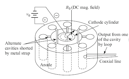
It is a diode usually of cylindrical configuration with a thick cylindrical cathode at the center and a co-axial cylindrical block of copper as an anode. In the anode, the block is cut a number of holes and slots which act as resonant anode cavities. The space between the anode and cathode is the interaction space and one of the cavities is connected to a coaxial line or waveguide for extracting the output. It is a cross-field device as the electric field between anode and cathode is radial whereas the magnetic field produced by a permanent magnet is axial. The permanent magnet is placed such that the magnetic lines are parallel to the vertical cathode and perpendicular to the electric field between cathode and anode.

Operation:
The cavity magnetron has cavities, which are tightly coupled to each other. It is commonly known that an N-cavity tightly coupled system will have N-modes of operation each of which is uniquely characterized by a combination of frequency and phase of oscillation relative to the adjacent cavity. In addition, these modes must be self-consistent so that the total phase shifts around the ring of cavity resonators are 2nπ, where n is an integer. For example, a phase shift should be 40o between cavities of a –cavity magnetron will mean that the first cavity is out of phase with itself by 320o. The correct minimum phase shift should be 45o (45×8 =320o). Therefore if ϕv represents the relative phase change of the AC electric field across adjacent cavities, then,
^{\phi_{\upsilon}}=\frac{2\pi n}{N} where,n=0,\pm 1,\pm 2,…,\pm (\frac{N}{2}-1),\pm \frac{N}{2}
i.e., N/2 mode of resonance can exist is N is an even number.
If n=\frac{N}{2}, {\phi_{\upsilon}}=\pi
This mode of resonance is called the π-mode.
If n=0, {\phi_{\upsilon}}=0
This is the zero mode, meaning there will be no RF electric field between anode and cathode (called fringing filed) and is of no use in magnetron operation.
Electrons Behavior in Magnetron
Depending on the relative strengths of the electric and magnetic fields the electrons emitted from the cathode and moving towards the anode will traverse the interaction space.
In the absence of a magnetic field (B=0), the electron travels straight from the cathode to the anode due to the radial electric field force acting on it (indicated by the trajectory ‘a’ in figure ). If the magnetic field strength is increased (i.e., for the moderate value of B) it will exert a lateral force bending the path of the electron as shown by path ‘b’ in the figure. The radius of the path is given by R=mv/eB, which varies directly with electron velocity and inversely as the magnetic field strength.
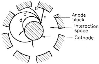
If the strength of the magnetic field is made sufficiently high so as to prevent the electrons from reaching the anode (as shown by path ‘c’ in the figure) the anode current becomes zero. The magnetic field required to return electrons back to cathode just grazing the surface of the anode is called the critical magnetic field (Bc), the cutoff magnetic field. If the magnetic field is made larger than the critical field (B> Bc), the electron experiences a greater rotational force and may return back to cathode quite faster. All such electrons may cause back heating of the cathode. This can be avoided by switching off the heater supply after the commencement of oscillation. This is done to avoid fall in the emitting efficiency of the cathode.
The π mode
The RF electric field between the two sidewalls of the entry points of a cavity is as in the figure at a particular moment. This field configuration will change with the frequency of the RF field shown inside the cavity is of TE110 mode in the cylindrical waveguide cavity resonator. In this mode, the phase difference (ϕ) between two adjacent cavities is π and is called π-mode. In higher modes, this difference ϕ has to be <π, but with the condition that 8ϕ = 2nπ, i.e., the total phase shift in the complete circle has to be multiple of 2π.
A typical characteristic of magnetron oscillator
- Frequency range: 0.5–75 GHz
- Efficiency: 40–70%
- Range of anode voltage (V0 ): 10–100 kV
- Anode current (I0): 10–100 A
- Cross-magnetic field (B0): 10–500 mWb/m2
- Duty Cycle: 0.1%
- Power Output: In excess of 250 kW (Pulsed mode), 10 mW (UHF Band), 2 mW (X Band), 8 kW (at 95 GHz)
Applications of Magnetron
- Voltage-tunable magnetrons (VTM’s) are used in sweep oscillators in telemetry and in missile applications with CW power at 70% efficiency in 0.2–10 GHz range.
- Continuous Wave (CW) fixed frequency magnetron is used in
- Industrial heating
- Transmitter
- Microwave oven at freq. 2.45 GHz and power = 600–1200 W. The efficiency is 64% or so. Therefore, the input dc power requirement is in the range of 1000– 2000 W depending on the size.
- Pulsed power magnetron of peak power of megawatts range is in RADAR.