Babinet’s Principle
Babinet’s principle states that the sum of the field at a point behind a plane having a screen and the field at the same point when a complementary screen is substituted is equal to the field at the point when no screen is present.
Salient features of Babinet’s principle
- It does not consider the polarization of antennas in establishing field relations.
- Basically it deals with absorbing screens only.
- It is useful to reduce the slot antenna problems to a simplified form like those of linear antennas.
- Babinet’s principle,
E3 = E1 + E2
Here, E1 is the field behind the absorbing screen
E2 is the field behind the complementary screen
E3 is the field when there is no screen.
- It is not applicable in the presence of the conducting screens.
- this principle is valid in optics.
- It cannot be extended to electromagnetic problems as it is not possible to have absorbing screens at radio frequencies and as the polarization of electromagnetic fields is common.
Meaning of Babinet’s principle
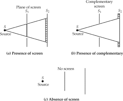
If, S1 is a plane of the screen,
S2 is a plane of observation,
S is a point source,
E1 is the field at a point (x, y, z) behind the screen,
E2 is the field at (x, y, z) behind the screen when S1 is replaced by its complementary screen,
E3 is the field at the same point (x, y, z) when no screen is present.
Babinet’s principle states that,
E3 = E1 + E2
This is illustrated in the figure below. This principle is valid at the points in the plane S2 and also at the points behind the screen S1.

This principle is applicable to the points in the plane S2 and also to the points behind the screen S1.
At radio frequencies, it is not possible to have perfectly absorbing screens. Hence, Babinet’s principle in optics cannot be just extended to the electromagnetic problem as it does not take care of polarisation.
A principle valid for conducting screens and polarised fields is described by H. G. Booker.
Illustration of Booker’s theory Booker’s extension of Babinet’s principle is illustrated below:
Consider three cases. The source is a short dipole that is shown in the figure below.
If the screen in an infinite conducting thin sheet with a vertical slot is considered, the field behind the screen at a point, P is E1.
If the slot is replaced by a complementary dipole (a thin strip of conducting sheet), the field is E2 at the same point, P behind the screen.
If there is no screen, the field is E3 at the same point. Then according to Babinet’s principle,
E1 + E2 = E3
The same principle can be applied to points in front of the screens. When the transmitted wave is very high through the slot, E1 ≈ E3. Under these conditions, the complementary dipole acts like a reflector and E2 is small.

When the screen and its complement are immersed in a medium whose intrinsic impedance is η, Zs and Zc are related by
Z_{s}.Z_{c}=\frac{\eta ^{2}}{4}