Table of Contents
Waveguide Discontinuities
Waveguide Discontinuities: Any interruption in the uniformity of a transmission line leads to impedance mismatch and is known as impedance discontinuity or waveguide discontinuities. In a waveguide system, when there is a mismatch, reflections will occur. In transmission lines, in order to overcome this mismatch, lumped impedances or stubs of required values are placed at the pre-calculated points. Some waveguide discontinuities are used for matching purposes.
Waveguide Irises
Fixed or adjustable projections from the walls of waveguides are used for impedance matching purposes, and these are known as windows or irises. An iris is a metal plate that contains an opening through which the waves may pass. It is located in the transverse plane of either a magnetic or an electric field. Irises are classified according to the sign of the imaginary part of the impedance. If the reactance of the impedance is positive or if the susceptance of the admittance is negative, we have an inductive iris. If the reactance is negative or if the susceptance is positive, we have a capacitive iris.
Inductive Iris
Usually inductive irises are used as coupling networks between half-wavelength cavities in rectangular waveguides. Generally an inductive iris is placed where either magnetic field is strong or electric field is weak. The plane of polarization of the electric field becomes parallel to the plane of inductive iris. This causes a current flow which sets up a magnetic field. Then the energy is stored in the magnetic field. Hence, inductance will increase at that point of the waveguide.

Capacitive Iris
A capacitive iris is also known as capacitive window as shown in figure below. It extends from the top and bottom walls into the waveguide. The capacitive iris has to be placed in strong electric field. This capacitive iris creates the effect of capacitive susceptance which is in parallel to that point of waveguide where the electric field is strong.

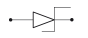
If the inductive and capacitive irises are combined suitably (correctly shaped and positioned), the inductive and capacitive reactances introduced will be equal, and the iris will become a parallel resonant circuit. For the dominant mode, the iris presents a high impedance, and the shunting effect of this mode will be negligible.

Other modes are completely attenuated, and the resonant iris acts as a band-pass filter to suppress unwanted modes. The figure shown below the series resonant iris that is supported by a non-metallic material and is transparent to the flow of microwave energy.

Tuning Screws and Posts
Posts and screws made from conductive material can be used for impedance-changing devices in waveguides. A post or screw can also serve as a reactive element. The only significant difference between posts and screws is that posts are fixed and screws are adjustable. A post (or screw) that only penetrates partially into the waveguide acts as a shunt capacitive reactance. When a post extends completely through the waveguide, making contact with the top and bottom walls, it acts as an inductive reactance. The screw acts similar to an LC-tuned circuit in such cases.
Screws
A screw is generally inserted into the top or bottom walls of the waveguide, parallel to the electric-field lines. It can give a variable amount of susceptance depending on the depth of penetration. A screw with an insertion distance (screw depth) less than λ/4 produces capacitive susceptance. When the distance is equal to λ/4, we have series resonance. When the distance is greater than λ/4, it produces inductive susceptance, as shown in figure below.

The adjustable waveguide screw is shown in Figure below. The capacitive setting shown in first figure and the inductive setting is shown in second figure.

The most direct method of impedance matching with a matched screw involves using a single screw that is adjustable in both length and position along the waveguide. However, it requires a slot in the waveguide.
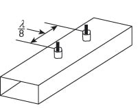
An alternative arrangement is to use double or triple screw units with a spacing of λ/8 or λ/4. A two-screw matcher is shown in Figure 6.7 (a).
Posts
A cylindrical post is introduced into the broader side of the waveguide; it produces a similar effect as an iris in providing lumped capacitive/inductive reactance at that point. When a metalpost extends completely across the waveguide, parallel to an electric field, it adds an inductive susceptance that is parallel to the waveguide. A post extending across the waveguide at right angles to the electric field produces an effective capacitive susceptance that is in shunt with the waveguide at the position of the post. The waveguide post is shown in figure below. The advantage of such posts over irises is the flexibility they provide, which results in ease of matching.

Matched Loads
The most commonly used waveguide terminations are the matched loads. Whenever the load impedance and characteristic impedance of the transmission line are not matched/equal, reflections exist. These reflections would cause frequency instability to the source. Matched loads are used for minimizing the reflections by placing a material in the waveguide parallel to the electric field to absorb the incident power completely.

One of the methods involved in the matched load is to place a resistive card in the waveguide parallel to the electric field as shown in above figure. The front portion of the card is tapered to avoid discontinuity of the signal, and it almost absorbs the incident field.
Related Posts: