Table of Contents
Transmission Errors
No physical medium can guarantee error-free transmission of data. Errors occur because of interference from the environment surrounding the transmission medium or because of artifacts introduced by the equipment or the medium itself. In case of copper wires, for example, thermal noise, electrical noise, and impulse noise are some of the most common causes: The networks must be able to transfer data from one device to another device with the complete accuracy. Many factors can alter or wipe out one or more bits of given data.
Transmission errors are caused by:
- Thermal noise (Shannon)
- Impulse noise (e.g., arcing relays)
- Signal distortion during transmission (attenuation)
- Crosstalk
- Voice amplitude signal compression (companding)
- Quantization noise (PCM)
- Jitter (variations in signal timings)
- Receiver and transmitter out of synch
Reliable systems must have a mechanism for detecting and correcting such errors. The most important role of the data link layer is to provide error-free transmission. To do this, it uses an error checking scheme to detect errors, and overcomes them by retransmitting corrupted frames. Many different error detection and correction methods have been devised.
Categories of Transmission Errors
Errors are introduced in the data bit during their transmission across a data network. These errors can be categorized as
- Content errors
- Flow integrity errors
Content Errors
Content errors are the errors in the content of a message e.g. a binary 1 may received as a binary 0. A block of data may have single bit error or multiple errors. Multiple errors is a data block are referred to as burst error. Length of burst error is defined from the first corrupted bit to the last corrupted bit. For example, burst error in shown below is six bits long. An error burst may contain un-corrupted bits as well

There can be several causes of content errors.
Signal Impairment: Distortion of electrical signal and noise are the main cause of content errors. Thermal noise causes sporadic bit errors. An impulse can last long enough to corrupt several bits and therefore leads to burst errors.
Loss of synchronization: The receiver samples the received signal to extract the digital information by using a clock that is synchronized to the clock loop. Too few transitions in extracted from the received signal using a filter and a phase lock loop.
Scramblers: Scramblers is used to ensure synchronization of transmitter and receiver clocks. It randomizes the serial data before its transmission. Strings of zeros and ones are thus avoided in the transmitted signal. Scrambling is done using a shift register and exclusive OR gates.
Scramblers have unfortunate property of multiplying errors If an error is received it gets multiplied as it shifts through the shift register. The errors multiplied depend on the number of taps taken from the shift register.
Transmission channel switching: Transmission channels of telecommunication network are usually protected, i.e. if the main path fails due to any reason the signals are switched over to standby path. The switchover may take about 10 to 50 ms, and it causes momentary loss of digital signal. These momentary disturbances are unnoticeable for voice channels but lead to burst error in data signals.
Flow Integrity Errors
Data is sent as data packets across a data network. It is not necessary that data packets sent by a source to the destination take the same path. In the figure shown below packet 1 goes via nodes A, B and D. Packet 2 goes directly from node A to node D. Packet 3 starts its journey from nodes A to D via nodes B and C. Flow of these data packers from the source to the destination may be affected in several ways.
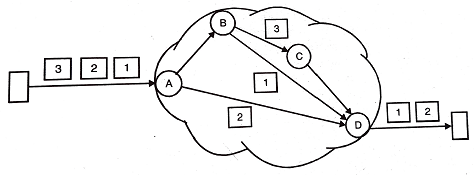
- The packets may be delivered out-of-sequence. Packet 2 takes shorter path and therefore it may arrive at node D ahead of packet 1.
- A data packet may not arrive at the destination at all. Packet 3 reaches up to node C, but is lost thereafter. Reasons of packet loss can be several:
- A packet may get corrupted due to content errors and may be rejected by a node.
- It may be delivered to wrong address due to errors that could not be detected.
- A node may not forward the packet due to congestion in the network. When a node experiences congestion (i.e. it has long queue of packets), it starts discarding data packets.
- Each data packet has limited lifetime in the network. Thus is called time to live (TTL). TTL can be defined in terms of number of hops. This is done to avoid circulating packets (packets that lose the way). A network node dumps all the TTL expired packers.
- The sender at times expects from the receiver an acknowledgement of having received a packet. If the acknowledge is not received within a defined time interval, the sender resends the packet. It may happen the receiver sends the acknowledgement, but the acknowledgement from the receiver is lost in the network. In such situation, the receiver will receive duplicate data packets eventually.
Thus a packed may be delivered to a wrong destination, or may be delivered out of sequence, or may not be delivered, or delivered in duplicate. All these are instances of flow integrity errors.
Systematic Code
Error detection and correction involves addition of check bits. A systematic code is a code in which each code word includes the unaltered data word followed or preceded by a separate group of check bits.
Types of Transmission Errors
There are two types of errors occur in data communication, namely:
- Single-Bit Error
- Burst Error
In case of single-bit error only one bit of the data is corrupted and rest all the bits are received correctly. That means only one bit from the data unit is changed either from 1 to 0 or 0 to 1.
For example, suppose the data frame 1111 is sent over the transmission line and at the receiver end the data frame is received as 1011. The second bit is changed from 1 to 0.
Single-bit error most likely to occurs when we send the data using parallel transmission mode. Suppose, if seven wires are connected to send all the 7 bits of a data unit at the same time and one of the transmission wire is noisy, one bit can be corrupted in each data unit. It is rare that we have single bit error in serial transmission mode. Imagine a sender sends data at 1 Mbps, that means each bit lasts only 1/1000000s i.e. 1ms. Now for a single bit error to occur, the noise duration must be 1ms, but practically the noise duration is much longer than this.
In case of burst error, multiples bits are corrupted and changed. For example, suppose data sent is 1111, received 0001. Three bits are changed from 1 to 0.
Example 1: Data sent 1 I 1 I Data received 000 I 3 bits are changed from 1 to 0
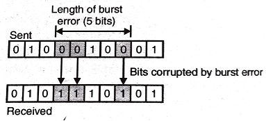
Let us discuss one more example of burst error, in this case data is sent 0100010001, but received as 0101110101. Three bits are changed from 0 to 1. From the example, a burst length also can be seen, i.e. 5 bits in this case.
Example 2: The burst length is measured from the first corrupted bit to the last corrupted bit. Some bits in between may be received correctly.
As we know that noise duration is more than the duration of one bit that means when noise affects data, it affects a set of bits. Serial transmission is most likely to be affected by the noise. It is obvious that the number of bits affected depends on the duration of noise and the data rate. Suppose we have data rate 1 kbps and a noise duration is 1/100s, than 10 bits are affected.
Error Detection
Error detection is the first stage of error correction. Error detection is simpler and easy than error correction.
There are some mechanism listed to detect the error in data communication based a concept of redundancy. In this concept a shorter group of bits may be appended to the end of each data unit before the transmission and they are discarded as soon as accuracy of the transmission has been confirmed.
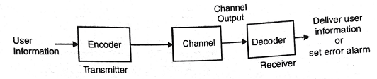
The above figure shows a general error detection system. In this figure, it is show n that user information is fed to encoder which will add some extra bits to the information and at the receiving end decoder, check the pattern.
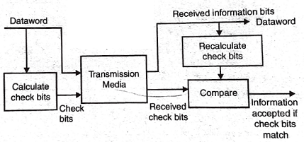
The above figure shows the detection system using check bits. In this system check bits are calculated and appended to the data word before transmitting to the receiver. At the receiver side, check bits are recalculated and with the received check bits. If check bits are same information is accepted otherwise it is discarded.
Types of Error Detection Techniques
Types of error detection techniques using Redundancy concept are as follows:
- Parity check
- Cyclic Redundancy Check
- Checksum
Parity Checking
Parity checking is a simple error detection method used with character oriented protocols. There are two types of parity checking techniques, such as Even parity and Odd parity. One bit in every character bit sequence is reserved for parity.
Cyclic Redundancy Check (CRC)
The CRC is a very powerful but easily implemented technique to obtain data reliability. The CRC technique is used to protect blocks of data Frames. Using this technique, the transmitter appends an extra n-bit sequence to every frame called Frame Check Sequence (FCS).
Checksum Codes
Another method for error detection is the use of checksum. Checksum have the advantage of operating on a long sequence of data.


