Table of Contents
Multiplexer (MUX)
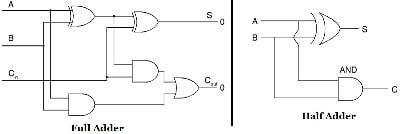
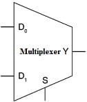
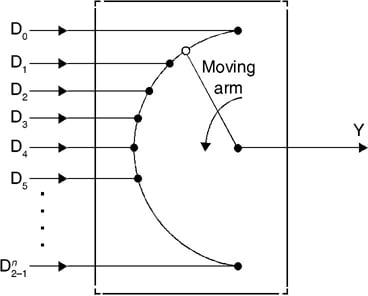
Multiplexers are combinational circuits that can select one desired input signal from among n inputs and passes it to the single output line. These are also called data selectors. They have 2n select lines, where n is the select lines or selector. The selection of the particular input to be passed to the output is controlled select inputs. The block diagram of a multiplexer is shown in the figure below.
2 × 1 MULTIPLEXER
Consider a 2 × 1 MULTIPLEXER, it has two input lines D0 and D1, one select input S, and one output line Y. The value assigned to S determines the output Y. The circuit is shown in the figure below .

When
- S=0, Then Y=D0
- S=1, Then Y=D1
Thus, the output signal is expressed as:
4 × 1 MULTIPLEXER
A 4 × 1 multiplexer as shown in the figure below, has four input lines D0, D1, D2, D3, two select inputs S0 and S1, and one output terminal Y.

The output here depends on the values taken by S0 and S1 which are represented in Table below.
| S1 | S0 | Y |
| 0 | 0 | D0 |
| 0 | 1 | D1 |
| 1 | 0 | D2 |
| 1 | 1 | D3 |
Thus, the output signal Y can be expressed as:
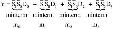
Therefore, in general, if the multiplexers have n select inputs, the output Y is given by:
Y=m_{0}D_{0}+m_{1}D_{1}+m_{2}D_{2}+.......+m_{2^{n}-1}D_{2^{n}-1}Where mi = ith minterm of the select inputs thus,
Y=\sum_{i=0}^{2^{n}-1}m_{i}D_{i}QUAD 2 × 1 MULTIPLEXER
Quad 2 × 1 multiplexers are used when we need to select any one of the two 4-bit numbers A and B based on some select signal S. The output Y is also a 4-bit number. The circuit is as shown in the figure below. The 4-bit output number Y will be equal to number “A” if the select line S = 0. When the select line S = 1 then the output is “B”.
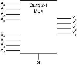
The circuit can be constructed using four 2 × 1 multiplexers, where the output of each of the multiplexers gives one of the outputs Yi.
Large multiplexers can be constructed by combining two or more small multiplexers. A 16 × 1 multiplexer can be constructed by using two (8 × 1 multiplexer) and one (2 × 1 multiplexer) as shown in the figure below.

Implementation of Boolean Functions Using Multiplexers
The primary function of multiplexers is its application as data selectors. Apart from working as data selectors, the multiplexers can be used in the execution of Boolean expressions. A Boolean function of X variables can be executed using a 2X input multiplexer. To perform logic functions, the data lines must be assigned logic high (1) or logic low (0). The inputs are applied to the select lines. As the number of variables keeps increasing, the data lines are also used to apply input variables.
Combinational Circuit Implementation using Multiplexers
Consider a function of n-variables. The multiplexers can be used to implement this function in two ways. Firstly, multiplexers can be chosen such that they have n-select inputs. The n variables can be connected to the n select inputs. The output Y is given as
Y=m_{0}D_{0}+m_{1}D_{1}+m_{2}D_{2}+.......+m_{2^{n}-1}D_{2^{n}-1}Alternatively,
Y=\sum_{i=0}^{2^{n}-1}m_{i}D_{i}Cascading Multiplexer Circuits
There can possibly be a situation where the desired number of input channels is not available in IC multiplexers. A multiple number of devices of a given size can be used to construct multiplexers that can handle a larger number of input channels. For instance, 8-to-1 multiplexers can be used to construct 16-to-1 or 32-to-1 or even larger multiplexer circuits. The basic steps to be followed to carry out the design are as follows:
- If 2n is the number of input lines in the available multiplexer and 2N is the number of input lines in the desired multiplexer, then the number of individual multiplexers required to construct the desired MUX circuit would be 2N−n.
- From the knowledge of the number of selection inputs of the available multiplexer and that of the desired multiplexer, connect the less significant bits of the selection inputs of the desired multiplexer to the selection inputs of the available MUX.
- The left-over bits of the selection inputs of the desired MUX circuit are used to enable or disable the individual multiplexers so that their outputs when ORed produce the final output.
Example 1
Implement the function F (A, B, C) = Σ (2, 3, 4, 5).
There are three variables A, B, C, and hence n = 3. This requires a multiplexer with 3 select inputs, i.e., an 8 × 1 multiplexer. Variable A is the most significant select input S2, while the least significant variable C is connected to the least significant select input S0, therefore,
S2 = A, S1 = B, and S0 = C
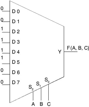
The multiplexer output expression (sum of minterms) includes minterm 1, we assign D1 = 2. Likewise, to include minterms 3, 4, and 5 in the sum of minterms expression, while excluding minterms 0, 1, 6, and 7, the following input (Di) assignments are made
- D1=D3=D5=D6=1
- D0=D2=D4=D7=0
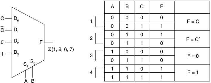
The second method by which multiplexers can be used to implement any logic function of n variables is by choosing the select inputs as (n – 1). A 3-variable function requires a 4 × 1 multiplexer. This is accomplished by choosing n – 1 variables to be connected to the multiplexer select lines. Then the truth table of the function is constructed by grouping the n – 1 select input variables together. The values of multiplexer input line Di will be 0, or 1, or nth variable or complement of nth variable in the given function F.
Consider the function F (A, B, C) = Σ (1, 2, 6, 7). The implementation of the function requires a 4-to-1 line multiplexer. A is applied to the select line S1 and B is applied to the select line S0. This is represented in the figure below.
Related Post:
Karnaugh Map (k-map) representation