An optical fibre is a flexible and transparent fibre, usually made of glass or plastic. It functions as a waveguide / light pipe to transmit light from one end of the fibre to another end using the fairly simple and relatively old technology of fibre optics which is based on refraction of light. It is used widely in transmission over long distances and high BW(bandwidth).
Optical fibre is a long, thin transparent dielectric material made up of glass or plastic, which carries electromagnetic waves of optical frequencies [visible to infrared] from one end of the fibre to the other by means of multiple total internal reflections. Thus, optical fibres work as waveguides in optical communication systems.
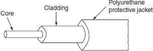
An optical fibre consists of an inner cylindrical material made up of glass or plastic called core. The core is surrounded by a cylindrical shell of glass or plastic called the cladding. The refractive index of core (n1) is slightly larger than the refractive index of cladding (n2), [i.e., n1 > n2]. Typical refractive index values are n1 = 1.48 and n2 = 1.46. The core diameter is ≈ 50 µm and the thickness of cladding is ≈ 1 or 2 wavelengths of light propagate through the fibre. The cladding is enclosed in a polyurethane jacket as shown in the figure below. This layer protects the fibre from the surrounding atmosphere. Many fibres are grouped to form a cable. A cable may contain one to several hundred such fibres.

Table of Contents
Working Principle of optical fibre
Once light rays enter into the core, they propagate by means of multiple total internal reflections at the core-cladding interface, so that the rays travel from one end of the optical fibre to the other. The phenomenon of total internal reflection in a straight optical fibre is explained in the following way. Let the refractive index of the core is n1 and that of the cladding is n2 such that n1 > n2. As shown in the figure below, a ray of light AO is incident at ‘O’ on the end face of the core; let this ray makes an angle of incidence θ0 with the axis of the fibre.
This ray is refracted into the core and passes along OB, the angle of refraction in the core is, say θ1. The ray OB is incident on the core-cladding interface with an angle of incidence, 90°-θ1. Suppose this angle of incidence is equal to the critical angle [θc= 90° − θ1] in the core at the core-cladding interface, then the angle of refraction in cladding is 90° so that the ray (BC) passes along the interface between core and cladding.
If the angle of incidence for a ray at the end face is less than θ0, then the angle of refraction is less than θ1 and angle of incidence at the core-cladding interface is larger than critical angle, so the ray suffers total internal reflection at the core-cladding interface. If the angle of incidence for a ray at the end face is larger than θ0, then the angle of refraction is larger than θ1 and the angle of incidence at the core-cladding interface is less than critical angle so that the ray will be refracted into the cladding and get lost in it due to absorption.

Light propagation in an optical fibre
So, all those rays which enter the core at an angle of incidence less than θ0 will have refracting angles less than θ1. As a result, their angles of incidence at the interface between core and cladding will be more than the critical angle. As a consequence, they will be totally reflected in core and travel by multiple total internal reflections.
Acceptance angle and acceptance cone:
As shown in the above figure, if the ray AO is rotated around the fibre axis keeping the angle of incidence θ0 constant, it results in a conical surface. As such, only those rays which are within this cone suffer total internal reflections so that they confine to the core for propagation. If a ray falls at the end face of the optical fibre at an angle greater than θ0 or out of the cone, that ray does not undergo total internal reflection at the core-cladding interface, it enters into cladding material and gets lost in the cladding material. Thus, for light rays to propagate through the optical fibre by total internal reflection, they must be incident on the fibre core within the angle θ0. This angle is known as acceptance angle.
Acceptance angle is defined as the maximum angle of incidence at the end face of an optical fibre for which the ray can be propagated in the optical fibre. This angle is also called acceptance cone half-angle.
A cone obtained by rotating a ray at the end face of an optical fibre, around the fibre axis with acceptance angle is known as acceptance cone. Expression for acceptance angle is obtained by applying Snell’s law at points B and 0°.
The equation for acceptance angle Sin \theta_{0}=\sqrt{n_{1}^{2}-n_{2}^{2}}
Numerical aperture (NA)
Numerical aperture represents the light-gathering capacity of an optical fibre. Light-gathering capacity is proportional to the acceptance angle, θ0. So, the numerical aperture can be represented by the sine of the acceptance angle of the fibre i.e., sin θ0.
Step index fibres and Graded-index fibres
Based on the variation of the refractive index of core, optical fibres are divided into
- Step-index and
- Graded-index fibres.
Again based on the mode of propagation, all these fibres are divided into (1) single-mode and multimode fibres. In all-optical fibres, the refractive index of cladding material is uniform. Now, we will see the construction, refractive index of core and cladding with a radial distance of fibre, ray propagation and applications of the above optical fibres.
Step index fibre
The refractive index is uniform throughout the core of this fibre. As we go radially in this fibre, the refractive index undergoes a step change at the core-cladding interface. Based on the mode of propagation of light rays, step-index fibres are of two types: (a) single-mode step-index fibres and (b) multimode step-index fibres. Mode means, the number of paths available for light propagation in a fibre. We describe the different types of fibres below.
(a) Single-mode step-index fibre:
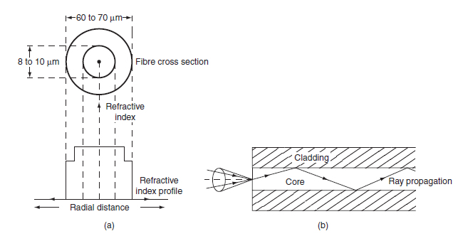
The core diameter of this fibre is about 8 to 10 µm and the outer diameter of cladding is 60 to 70 µm. There is only one path for ray propagation, so, it is called single-mode fibre. The cross-sectional view, refractive index profile and ray propagation are shown in the figure below. In this fibre, the transmission of light is by successive total internal reflections. i.e., it is a reflective type of fibre. Nearly 80% of the fibres manufactured today in the world are single-mode fibres. So, they are extensively used. Lasers are used as a light source in these fibres. These fibres are mainly used in the submarine cable system.
(b) Multimode step-index fibre:
The construction of multimode step-index fibre is similar to single-mode step-index fibre except that its core and cladding diameters are much larger to have many paths for light propagation. The core diameter of this fibre varies from 50 to 200 µm and the outer diameter of cladding varies from 100 to 250 µm. The cross-sectional view, refractive index profile and ray propagation are shown in the figure below. Light propagation in this fibre is by multiple total internal reflections. i.e., it is a reflective type of fibre. It is used in data links which have lower bandwidth requirements.

(c) Transmission of signal in step-index fibre:
Generally, the signal is transmitted through the fibre in digital form i.e., in the form of 1’s and 0’s. The propagation of pulses through the multimode fibre is shown in the above figure. The pulse which travels along path 1 (straight) will reach first at the other end of the fibre. Next, the pulse that travels along path 2 (zig-zag) reaches the other end with some time delay. Lastly, the pulse that travels along path 3 reaches the other end. Hence, the pulsed signal received at the other end is broadened. This is known as intermodal dispersion. This imposes a limitation on the separation between pulses and reduces the transmission rate and capacity. To overcome this problem, graded-index fibres are used.
Graded index fibre:
In this fibre, the refractive index decreases continuously from centre radially to the surface of the core. The refractive index is maximum at the centre and minimum at the surface of the core. This fibre can be single mode or multimode fibre. The cross-sectional view, refractive index profile and ray propagation of multimode graded-index fibre are shown in the figure below. The diameter of core varies from 50 to 200 µm and the outer diameter of cladding varies from 100 to 250 µm.
The refractive index profile is circularly symmetric. As refractive index changes continuously radially in the core, the light rays suffer continuous refraction in the core. The propagation of light rays is not due to total internal reflection but by refraction as shown in the figure below. In graded-index fibre, light rays travel at different speeds in different parts of the fibre. Near the surface of the core, the refractive index is lower, so rays near the outer surface travel faster than the rays travel at the centre. Because of this, all the rays arrive at the receiving end of the fibre approximately at the same time. This fibre is costly. Either laser or LED is used as the light source. Its typical applications are in the telephone trunk between central offices.

Transmission of signal in graded-index fibre: In multimode graded-index fibre, a large number of paths are available for light ray propagation. To discuss intermodal dispersion, we consider ray path 1 along the axis of the fibre as shown in the above figure and another ray path 2. Along the axis of the fibre, the refractive index of the core is maximum, so the speed of ray along path 1 is less. Path 2 is sinusoidal and it is longer; along this path refractive index varies. The ray mostly travels in low refractive index region, so the ray 2 moves slightly faster. Hence, the pulses of signals that travel along path 1 and path 2 reach another end of fibre simultaneously. Thus, the problem of intermodal dispersion can be reduced to a large extent using graded-index fibres.
Advantages of Optical Fiber
The main advantages of optical fibre are:
- Bandwidth: optical systems have a higher bandwidth than any other system of telecommunication. Many more signals can be frequency multiplexed or time multiplexed on to a single channel. This allows the development and implementation of highly complex stacking systems.
- Cable cost: the cost of optical fibre is greater than that of copper cable, but it is falling. Offset this against the fact that, over long distances, repeater stations can be up to 160 km apart. Often they are much closer than this because the power for the repeater unit is supplied along a pair of copper wires running in the cable alongside the fibres. This limits the distance between repeaters to 10 km. Local power supplies are used if the distance between repeaters is greater than this. Even so, optical fibres give longer runs compared with copper cables, which need repeaters every few kilometres.
- Immunity from EMI: unlike copper cable, optical fibre is immune from the effects of external electromagnetic fields. It is particularly suited to industrial applications where electrical machinery and heavy switching generate strong interference. There is no crosstalk between fibres bundled in the same cable.
- Safety: faults in copper cabling may generate excess heat, which may lead to fire. This is much less likely to occur with optical fibre.
- Security: surveillance equipment can be used to read, messages being transmitted on copper cables. This is not possible with optical fibre.
- Corrosion: unlike copper cable, optical fibre does not corrode.
Applications of Optical Fiber
Fibre optic cables find many uses in a wide variety of industries and applications. Some uses of fibre optic cables include:
- Medical: Used as light guides, imaging tools and also as lasers for surgeries
- Defence/Government: Used as hydrophones for seismic waves and SONAR , as wiring in aircraft, submarines and other vehicles and also for field networking
- Data Storage: Used for data transmission
- Telecommunications: Fiber is laid and used for transmitting and receiving purposes
- Networking: Used to connect users and servers in a variety of network settings and help increase the speed and accuracy of data transmission
- Industrial/Commercial: Used for imaging in hard to reach areas, as wiring where EMI is an issue, as sensory devices to make temperature, pressure and other measurements, and as wiring in automobiles and in industrial settings
- Broadcast/CATV: Broadcast/cable companies are using fibre-optic cables for wiring CATV, HDTV, internet, video-on-demand and other applications
