Table of Contents
Cathode Ray Oscilloscope (CRO)
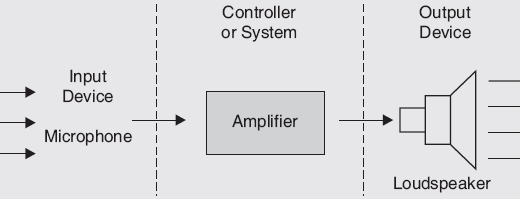
Cathode Ray Oscilloscope (CRO): The CRO stands for a cathode ray oscilloscope. Cathode Ray Oscilloscope (CRO) is a device that is used for showing the signals on the screen. In 1879, Willan Crooks demonstrated that the cathode rays can be reflected in a vacuum tube type by using a magnet. Basically, It has four parts which are display, vertical and horizontal deflection plates, Triggers, and Electron Gun. The oscilloscopes have used the probes which is coaxial cable and these cables are used for taking input from or giving output to any instrument. With the help of an oscilloscope, we can analyze the waveform by plotting amplitude along with the x-axis and time on the y-axis. The major applications of CRO are in TV receivers and also in laboratory work involving research and design. It also plays a major role in the medical science field.

Lissajous Figures or Lissajous Patterns
What is a CRO?
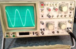
Cathode Ray Oscilloscope (CRO) is basically a graph displaying device. It draws a graph of an electric signal. It is an electronic test instrument, which is used to obtain waveforms when the differential input signals are given. The vertical axis (Y) represents Voltage and the horizontal axis (X) represents time. The intensity or brightness of the display is sometimes called Z-axis. The oscilloscope shows the variations in the electrical signals over time, thus the voltage and time describe a shape and it is continuously graphed beside a scale. From the screen of the oscilloscope, we can easily see some properties like amplitude, frequency, time interval and etc. The Oscilloscope is used for finding the frequency and time period of any wave. We can also check the electronic components very easily.
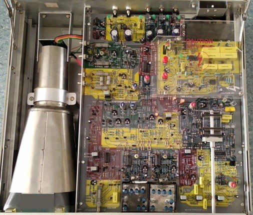
Inside CRO
Block Diagram of CRO
The block diagram shows the general purpose of CRO internal contraction. The CRO has the cathode ray tube which acts as the heart of the oscilloscope. In an oscilloscope, the CRT produces the electron beam which is accelerated, decelerated, and focus with the help of accelerating and focusing anode at a high velocity and brings to the focal point on a fluorescent screen. After the collision of the electron on the screen, it produces a visible spot where the electron beam strikes with it and this spot is seen on another side of the screen. This collision or bombarding of electrons is continually done on the screen which shows the electrical signal, this electron beam is like an electrical pencil of light that produces a light where it collides with the screen.

For the completion of this task, we need many electrical signals. These electrical signals have many levels of voltages. The oscilloscope needs high voltage and low voltage for the complete display of the signal on the screen. The low voltage which is directly supplied to the mains supply is used for the heater of the electron gun to generate the electron beam. A high voltage is required for the cathode ray tube to enhance the speed of the beam and avoid secondary emission. The normal voltage supply is used for other controlling units of the CRO. The horizontal deflection plates and vertical deflection plates are placed between the electron gun and the screen, which are used to control the position of the electron beam as per the requirement of the electrical signal. The trigger circuit is used for synchronizing both axis i.e. X and Y-axis. So the electron beam strike on the desired position of the screen.
The major blocks in general-purpose CRO are
- Cathode Ray Tube (CRT)
- Horizontal Deflection System
- Vertical Deflection System
- Power Supply
1. Cathode Ray Tube (CRT)
CRT is an essential part of CRO. This is also used in the Monocreme picture tube. CRT consists of an electron gun that produces an electron beam. This is a narrow beam that passes through the tube and falls on the screen. The point at which the electron beam will strike that point will glow due to the coating of fluorescent material on the screen.
The main parts of CRT are –
- Electron Gum Assembly
- Deflection plate assembly
- Fluorescent Screen
- Glass Tube

2. Horizontal Deflection System
It has the following blocks
- Time Base Generator
- Trigger Circuit
- Horizontal Amplifier
Time Base Generator
A time Base Generator is used to generate a sawtooth voltage which is applied to horizontal deflection plates. Which is generated due to the voltage decrease to zero must be fast so the beam can very rapidly move from right to left.
Trigger Circuit
Trigger Circuit triggers the time base generator to generate a sawtooth waveform when the vertical input signal is present. It is used to convert the incoming signal into a trigger pulse so that the input signal and the sweep frequency can be synchronized.
Horizontal Amplifier
A horizontal Amplifier is used to amplify the sawtooth voltage before it is applied to horizontal deflection plates.
3. Vertical Deflection System
It consists of the following parts Attenuator Vertical Amplifier Delay Line
Attenuator
An attenuator is a voltage divider network consisting of a number of resistors. By selecting the proper resistor, the corresponding voltage is obtained.
Vertical Amplifier
A vertical Amplifier is a wideband amplifier used to amplify the signal in the vertical section of the signal.
Delay Line
Delay Line is used to delaying signals for some time in the vertical section.
4. Power Supply
There are two power supplies-
a) Negative high voltage (HV) Supply
b) Positive low voltage supply (LV). The +ve voltage supply is from +300V to 400V, the negative voltage supply is from -1000 V to -1500 V.
Applications of CRO
- Voltage measurement
- Current measurement
- Identification of waveform
- Measurement of phase and frequency using Lissajous pattern
- Component Testing
You may also like in Hindi click here