Table of Contents
Conversion of Flip-Flops
The conversion of flip-flops from one type to another is done by connecting a combinational circuit prior to the flip-flop. The output of the combinational circuit is given to the input of the flip-flops. While designing a flip-flop, the excitation tables for both flip-flops are combined and a truth table is made for the data inputs and data outputs. It is then reduced into the K-map and the best logic circuit is deduced. The inter-conversion of the flip-flops is discussed below.

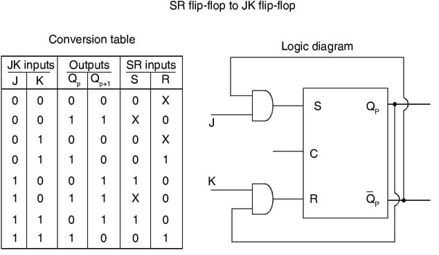
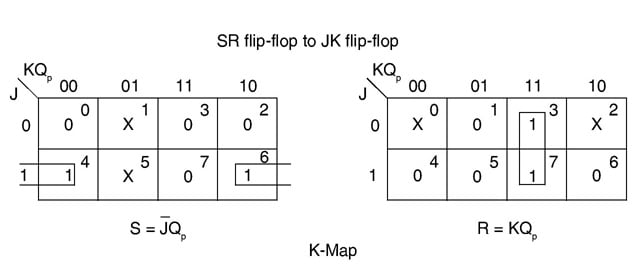
SR Flip-Flop to JK Flip-Flop
The conversion of an RS flip-flop into JK flip-flop requires that the inputs of RS flip-flops will be from the combinational circuit and JK flip-flop. As shown in the logic diagram below in figure, S and R will be the outputs of the combinational circuit. The truth tables for the flip-flop conversion are given below. The present state is represented by Qp and Qp + 1 is the next state to be obtained when the J and K inputs are applied. For two inputs J and K, there will be eight possible combinations. In each combination of J, K, and Qp, the corresponding Qp + 1 states are found. Qp + 1 implies the future states that the JK flip-flop takes. The table is then completed by writing the values of S and R required to get Qp + 1 from the corresponding Qp.
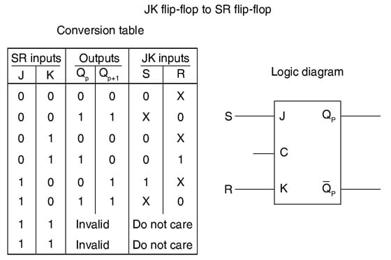
JK Flip-Flop to SR Flip-Flop
Here the conversion of flip flops is obtained by reversing the conversion process where S and R will be the external inputs to J and K. Now J and K will be the outputs of the combinational circuit. Hence the output value of JK flip-flop is defined by S, R and Qp. Truth table, logic circuit and K-map for JK Flip-flop to SR Flip-flop is shown below in figure.
A conversion table is to be written using S, R, Qp, Qp + 1, J, and K. For two inputs, S and R, eight combinations are made. For each combination, the corresponding Qp + 1 outputs are found. Here both S and R cannot be maintained at logic high which happens to be a forbidden state. Thus, the outputs are considered invalid and the J and K values are taken as “don’t care”.

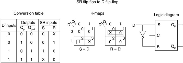
RS to D Flip-Flop:
The RS inputs are interconnected. D input is the given to it. D is the external input of the flip-flop and there are four possible combinations. The logic diagram, conversion table, and K-map are shown below figure.
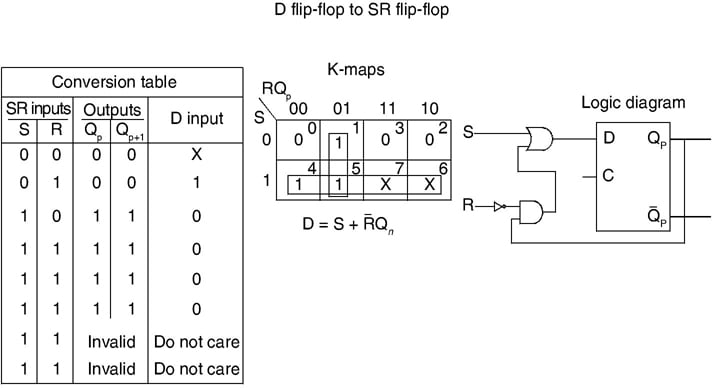
D Flip-Flop to SR Flip-Flop
Now D is the actual input of the flip-flop and S and R are the external inputs. It has eight possible combinations in the truth table depending on S, R, and Qp. Again the combination of S = 1 and R = 1 are invalid, the values of Qp + 1 and D are considered as “don’t care”. The logic diagram showing the conversion from D to SR, and the K-map for D in terms of S, R, and Qp are shown in the figure below.
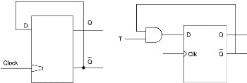
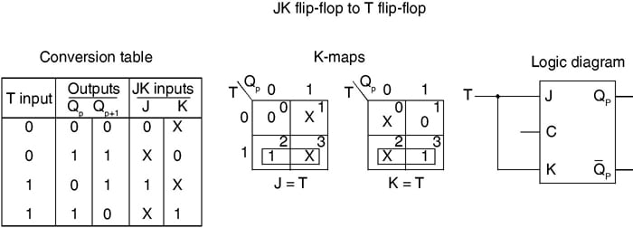
JK Flip-Flop to T Flip-Flop
JK inputs are interconnected and T is the external input for conversion. Four combinations are produced with T and Qp. J and K are expressed in terms of T and Qp. The conversion table, K-maps, and the logic diagram are given below in the figure below.
JK Flip-Flop to D Flip-Flop
D is the external input and J and K are the actual inputs of the flip-flop. D and Qp make four combinations. J and K are expressed in terms of D and Qp. The four combination conversion table, the K-maps for J and K in terms of D and Qp, and the logic diagram showing the conversion from JK to D are given below in figure below.

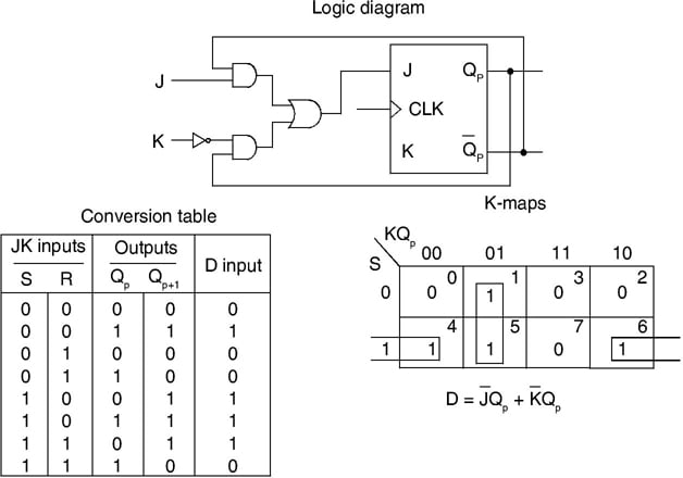
D Flip-Flop to JK Flip-Flop
In this conversion, D is the actual input to the flip-flop, and J and K are the external inputs. J, K, and Qp make eight possible combinations, as shown in the conversion table below. D is expressed in terms of J, K, and Qp. The conversion table, the K-map for D in terms of J, K, and Qp, and the logic diagram showing the conversion from D to JK are given in the figure below.