Table of Contents
Composite Video Signal
Composite video signal comprises of a camera signal relating to the desired picture data, blanking pulses to make the retrace invisible, and synchronizing pulses to synchronize the transmitter and receiver scanning. A horizontal synchronizing (sync) pulse is required toward the finish of every active line period whereas a vertical sync pulse is required after each field is scanned.
In other words the picture information is not transmitted alone. They carries the various signals along with such as the blanking pulses to make the retrace invisible and synchronizing pulses to synchronize the scanning at the transmitter and at the receiver. All the components all together are known as Composite Video Signal (CVS).
Composite video signal consists of
- A camera signal corresponding to the desired picture information,
- Blanking pulses to make the retrace invisible and
- Sync pulses to synchronize the Tx & Rx scanning.
Composite video signal can be represented either with positive polarity or with negative polarity.
Positive Polarity
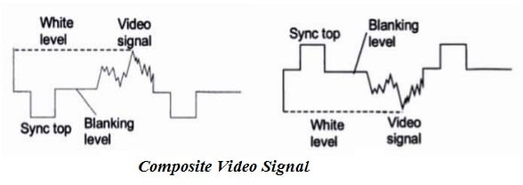
In the case of Positive polarity, whiter the scene, higher is the amplitude of the video signal. Blanking level is kept at the zero level. Below zero level is the sync pulse. Sync top is at the most negative point as shown in figure below.
In case when the video signal is produced by photo conduction type camera tubes, bright white light gives a high amplitude of video signal. At the receiver; for reproducing white on the fluorescent screen, a stronger signal is needed and for reproducing black, zero signals are needed,

Negative Polarity
In case of negative polarity, brighter the scene, smaller is the amplitude. Here sync pulse is positive, that is above the blanking level. Black is just below the blanking level. Brighter the scene, lower is its level below the blanking level. White is near the bottom.

The modulation of the RF carrier by the CVS is in the form of negative AM, where bright picture points correspond to low carrier amplitude and the sync pulse to maximum carrier amplitude. This type of modulation is called Negative Modulation.
In most of the TV systems, negative polarity is used to modulate the video carrier.
Advantages of Negative Modulation
- In the case of negative modulation, the noise pulses in the transmitted signal shall increase the amplitude of the carrier which will move towards the black. Thus noise falling in dark grey or black region will not cause irritation. But in positive modulation, white blobs will be caused in the picture due to random noise signals.
- In negative modulation the voltage of the blanking pulse is of fixed level which depends on the carrier strength. Thus this level forms the reference level for deriving AGC (automatic gain control) voltage dependent on the carrier strength.
- The amplitude of the Carrier will remain low for most of the time as the signal content is more in white than in black. This will save the transmission power.
Disadvantages of Negative Modulation
- Picture tube i.e. cathode ray tube needs positive polarity between control grid and cathode. So the negative polarity of the video signal is to be changed to positive polarity before feeding to the control grid.
- High impulse pulse may disturb the H-sync and hence horizontal-synchronization may be disturbed for a short duration. This effect is reduced by using automatic frequency control in sweep circuits in the receiver.
In spite of these disadvantages, we use negative modulation in all TV systems because it has more advantages.
Video Signal Dimensions
The Voltage levels tor sync pulse, blanking pulse and video are different, so that these pulses can be separated easily in the receiver. Voltage division multiplexing is used to keep these pulses and signal at different levels in CVS. There are two ways of indicating the levels:
- Percentage of carrier (for modulated signals).
- Institute of Radio Engineers (IRE) scale (for video base band signal)
Percentage of Carrier
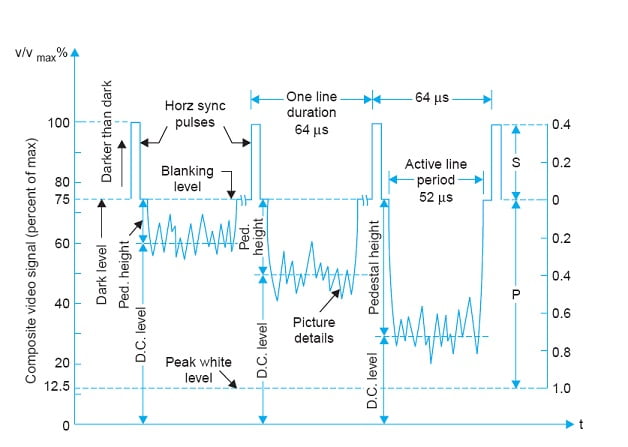
For modulated signal, the various pulse levels are indicated in terms of percentage of carrier level. For positive polarity, white level is at 90%, whiter than white goes up to 100%, blanking level is at 75% and sync pulse top is at 0%.
Peak White Level
Peak White Level is the level of video signal when the picture information being transmitted corresponds to the maximum whiteness. This level is fixed at 10 to 12.5% of the maximum value of the signal.
Whiter than White
The signal level below the peak white level i.e. form 10% to 0% level is referred as whiter than white level.
Black Level
The negative modulation, the black or dark level shown at 72% of the maximum level.
Blacker than Black
Signal beyond the black level from 72% to 100% of the maximum signal level is known as Blacker than Black level.
Blanking Level
The blanking level in composite video signal is represented by 75% of the carrier level. This level is also known as pedestal level.
Sync Pulses
Sync pulses are added at 75% and sync top level is at 100%.
DC Components of the Video Signal
Since the amplitude of various picture elements varies continuously, the video signal has an average brightness of the scene. Rx cannot follow the changes in brightness, if the dc component is not present. Average brightness can change only from frame to frame but not from line to line.
Pedestal Height
Video signal corresponding to picture information varies in accordance with the variation of intensity light at various picture elements. Pedestal height is the difference between pedestal level and the average value of the video signal. Pedestal level may h used as a reference level to indicate average brightness of the signal.
The ratio of Picture Information to Sync Pulse Amplitude
Sync pulses are required at the horizontal and vertical traces to trigger the respective scanning oscillators. During the trace, the video signal changes between white and black levels.
Upper 25% is occupied by sync pulses and 65% of the carrier amplitude is occupied by the video signal. The transmitted signal has a picture to sync (P/S) ratio is equal to 10/4.
The overall arrangement of combining the picture signal and sync pulses may be considered as a kind of voltage division multiplexing.
If sync pulse amplitude is increased to reduce the ratio say to 10/7, the contrast’ the picture will be degraded.
If the picture information is increased to increase the above ratio, sav 10/3, the sync pulse amplitude would become inadequate to keep the picture stable.
Thus the ratio of 10/4 is optimum.
Three brightness level of the Composite Video Signal shown below.

For negative polarity sync top is at 100%, blanking level is at 75%, white level is at 10% and whiter than white is below 10%.
- Peak white level: 10 to 12.5 %
- Blanking level: 75 % (also known as Pedestal level)
- Sync pulses: 75 to 100%
- Black level: 72%
- Pedestal: The difference between blanking level and black level.
- Blacker than black: 72 to 100 %
- Whiter than white: signal below 10 % to 0 %
NOTE :
To minimize the noise effect the lowest 10% of the voltage range is not used. At the Rx picture tube is biased to ensured that a received video voltage corresponding to about 10% modulation yields complete whiteness at the particular point on the screen.
Blanking Pulse
The composite video signal contains blanking pulses to make the retrace lines invisible by raising the signal amplitude slightly above the black level (75%) during the time the scanning circuits produce retraces.
The repetition frequency for;
- Horizontal blanking pulse : 15625 Hz
- Vertical blanking pulse : 50 Hz
Blanking pulse period for
- Horizontal blanking pulse : 12 µs
- Vertical blanking pulse : 1280 µs
The figure of details of horizontal and vertical blanking pulses shown below.

Related Posts

