Table of Contents
Waveguide
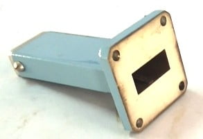
A waveguide is just a hollow metallic tube that may be rectangular or circular in shape and is used to guide the microwaves. Waveguides are constructed of brass, copper, or aluminum. The inner surface of the waveguide is usually coated with either gold or silver.
Waveguides are primarily used at microwave and optical frequency ranges, whereas transmission lines are used at lower frequencies. In practice, the required operating frequency band and the amount of power to be transferred are the main basis for choosing the structure. The cause for the inefficiency of Transmission lines is the skin effect and dielectric losses.
In waveguides, the electromagnetic (EM) waves are propagated in a bounded medium. So, no power is lost due to radiation. Since the guides are generally air-filled, the dielectric loss is negligible. However, some power is lost as heat in the walls of the guides owing to the skin effect. This loss in the walls is negligible.
The EM waves can be propagated in several modes within a waveguide, namely, in the Transverse Electric (TE) and Transverse Magnetic (TM) modes. The TE wave has the electric field only in the plane that is transverse to the direction of propagation (i.e. the longitudinal components, Ez = 0 and Hz ≠ 0). The TM wave has only the magnetic field in the transverse plane (i.e. in the direction of propagation, Hz = 0, and Ez ≠ 0). These modes are dependent on the solutions of Maxwell’s equation for the given waveguide.
Every mode has a particular cut-off frequency, and this cut-off frequency is dependent on the physical dimensions of the waveguides. Below the cut-off frequency, it does not transmit signals. The dominant mode is the mode having the lowest cut-off frequency. In further sections, different types of modes and their corresponding cut-off frequencies are explained for various types of waveguides.
Types of Waveguide
The shape of the waveguide decides the functionality of the given waveguide. The cross-section of the waveguide can be of any shape. However, since irregular shapes are difficult to analyze, they are rarely used. The three most commonly used shapes are as follows:
- Rectangular waveguides Both TE and TM modes can be supported by these waveguides. The electric field is transverse to the direction of propagation in TE modes. The magnetic field is transverse to the direction of propagation in TM modes.
- Circular waveguides: They tend to twist the waves as they travel through them and are used with rotating antennas in radars.
- Elliptical waveguides: An elliptical shape is often preferred in flexible waveguides. These waveguides will be required whenever its section is capable of movement, such as bending, stretching, or twisting.

Rectangular Waveguide
A waveguide which is a hollow metallic tube of a rectangular cross-section is known as the rectangular waveguide. The EM fields can be confined. Therefore, the EM waves can be guided by the walls of the guide through reflections. Rectangular waveguides are usually made in standard sizes with breadth “a” (along x-direction) approximately twice the height “b” (along y-direction). The “a” dimension cannot be less than a one-half wavelength. This can be seen, as the guide is made up of two-quarter wavelength stubs separated by a small distance. Any frequency that makes the “a” dimension less than one-half wavelength allows no propagation of energy down the waveguide.

Mode of Propagation
A mode of propagation is nothing but a distinct field pattern. There are four different mode categories.
TEM Mode or Principal Mode (Ez = 0 and Hz = 0)
In this mode, both the E and H fields are transverse to the direction of wave propagation, and this is known as the transverse electromagnetic (TEM) mode. Due to Ez = 0 and Hz = 0 in this mode, all field components are reduced to zero, so that there is no field component along the direction of propagation. Thus, from the result, a rectangular waveguide cannot support the TEM mode.
TE modes (Ez= 0 and Hz≠ 0)
In this mode Ez = 0, at all points within the waveguide. This means that there is no electric field vector component along the direction of propagation, and the magnetic field vector is along the direction of propagation.
TM modes (Ez≠ 0 and Hz= 0)
In this mode Hz = 0 at all points within the waveguide. This means that there is no magnetic field vector component along the direction of propagation, and the electric field vector is parallel to the long axis.
HE modes (Ez≠ 0 and Hz= 0)
In this case, neither E nor H field is transverse to the direction of wave propagation, and they are known as hybrid modes.
Circular Waveguide
A circular waveguide is a hollow metal tube with a circular cross-section. It is basically a tubular, circular conductor. This is used only for some special applications. For example, it is used in a rotating joint, which transmits an electromagnetic wave to the feeder of a rotating radar antenna. In circular waveguides, the plane of polarization is not stable due to geometry. The frequency band of the single-mode operation of a circular waveguide is narrower than the same band of a rectangular waveguide.

Comparison between the rectangular and circular waveguide
Rectangular waveguide preferred over circular waveguides:
- For a similar operating frequency, a rectangular waveguide is not suitable in some applications as it is smaller in size than a circular waveguide.
- The polarization is not maintained by the wave through the circular waveguide; i.e, the circular symmetry of the waveguide may reflect the possibility of the wave without maintaining its polarization throughout the length of the guide.
- The frequency difference between the lowest frequency in the dominant mode and the next mode of rectangular waveguides is bigger than that in circular waveguides.
Circular waveguides preferred over rectangular waveguides:
- First is their shape, the use of circular terminations and connectors is allowed, which are easier to manufacture and attach.
- Due to the TE01 mode in the circular waveguides, which has the lower attenuation per unit length of the waveguide, these are suitable for long-distance communications.
- The rotary joints are also made by the circular waveguides, which are needed when a section of the waveguide should be able to rotate, such as for the feeds of revolving antennas.