Table of Contents
Tunable Optical Filters
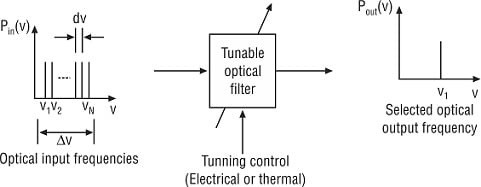
Tunable optical filters are active components that are mostly used at the receiver end of a WDM system. As the name suggests, its main function is to get tuned and select a desired optical channel from the multiplexed received signal. Tunable optical filters have the ability to change the wavelength they select dynamically. The bandwidth of the tunable optical filter should be properly designed for a particular channel being selected. It should be sufficiently large so that the desired optical channel can pass through without much loss of the signal. On the other hand, it should be relatively small so that it can adequately reject the adjacent channel. The primary operation of the tunable optical filter is illustrated in the figure below.

Tunable filters are made by changing at least one branch of an interferometry optical filter in terms of either its refractive index or length of the propagation path using some control mechanism. When these parameters vary, the phase, as well as the intensity of the propagating light wave, changes as a function of wavelength. In this way, the wavelength selectivity is achieved.
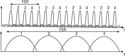
To increase the number of channels, tunable optical filters can be cascaded having different values of free spectral range (FSR). For example, four optical channels of a high-resolution optical filter can be cascaded with four optical channels of a low-resolution optical filter within FSR, which results in 16 unique channels. It is shown below.

Desirable Properties
- Wavelength tunability (nm) for dynamic operation (i.e., wide tuning range). Typical tuning range (Δn) is specified as 25 THz (or 200 nm) for 1330–1500 nm optical band. This enables for maximizing the number of selectable optical channels in WDM systems. With EDFA, normally Δl = 35 nm centered at 1550 nm.
- Channel Spacing (dn): The minimum separation between channels selected to minimize crosstalk (desirable 30 dB or better)
- Maximum number of channels (N = Δn/ dn)
- Flat passband and steep slopes
- Relatively faster tuning speed (usually in milliseconds) that enables to minimize the access time
- Low insertion loss
- Negligible cross-talk
- Insensitive to polarization of optical signals
- Stable operation
- Small size and low cost
Classification of Tunable Optical Filters
(a) Tunable optical filters based on optical interference
- Fabry–Perot Interferometer (FPI)
- Mach–Zehnder Interferometer (MZI)
(b) Tunable optical filters based on optical diffraction
- Grating-based Michelson
- Acousto–optic
- Electro–optic
Fabry–Perot Interferometer Filters
An FPI tunable optical filter basically comprises a cavity that is constructed by using two mirrors at either end. The length of the cavity is electronically adjusted with the help of a piezoelectric transducer. The figure is shown below a Fabry–Perot interferometer tunable optical filter and its transfer function.

Free spectral range (FSR) is an important parameter of a Fabry–Perot filter that is used to define the separation between periodic transmission peaks. It is given by
FSR=\Delta \nu _{L}=\frac{c}{2n_{g}L}where, ng represents the group refractive index, and L represents the cavity length.
The FPI filter bandwidth DnFP, or approximate bit rate RB should be very large so that all the frequency components of the selected channel are passed. That is,
\Delta \nu _{L}-R_{B}=\frac{\Delta \nu _{L}}{F}where, F represents the finesse of FP filter which is expressed as F=\frac{\Delta \nu _{L}}{\Delta \nu _{FP}}
Neglecting the internal losses, the parameter ‘finesse’ of FP filter is given by
F=\frac{\Pi \sqrt{R}}{\sqrt{(1-R)}}where, R represents the mirror reflectivity.
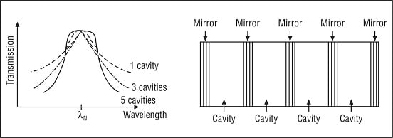
An FPI filter uses two different optical fibers having an air gap in between. The two ends of the optical fiber are coated in such a way that they can act as highly reflective mirrors that can reflect optical signals. Then, the whole assembly is encapsulated within a chamber made of piezoelectric material. The length of the air gap length is varied electronically to enable tuning of a specified optical channel. Typical transmission characteristics along with an arrangement of multi-cavity thin film optical filter are depicted in the figure below.

Advantages of FP Interferometer Filters
- Wide dynamic range
- Narrow bandwidth
- High tuning speed
- Low polarization-dependent loss (PDL)
Disadvantages of FP Interferometer Filters
- a limited number of channels, typically less than 100 (F ≈155)
- Relatively slow tuning due to mechanical nature
- Poor stability
- Low sidelobe suppression ratio (SSR)
Mach–Zehnder Interferometer Filters
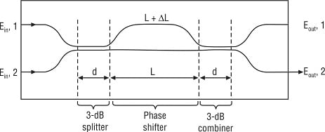
MZI tunable optical filters can be realized when two ports of a 3-dB optical coupler at its output are connected to two output ports of a second 3-dB optical coupler. Such an arrangement is depicted in the figure below.
Tuning over the desired optical range can be obtained by varying the refractive index of one of the arm of MZI either by heating it, or by placing Electro–optic material (e.g., lithium niobate, LiNbO3).
By applying drive voltage to one of the two waveguides, an electric field is created. As a result, the signals that appear at the output of two waveguides will have either in-phase (0° phase shift), or 180° phase shift. Accordingly, the optical signal will be either passed or blocked.

A cascaded chain of MZ interferometer tunable optical filters with their relative delays is adjusted suitably. Tuning is carried out by varying the length of arms slightly that can achieve Finesse value of
1600. MZ chain comprises of a splitter, a combiner and a delay. The adjustable delay controls one of the path lengths that may result in a phase difference when combined. Wavelengths with 180° phase difference are filtered out. It is capable of selecting closed spaced channels (suitable for DWDM applications). However, it exhibits a slow response (~ 1 ms) because of thermal tuning mechanism, therefore, low tuning speed.
Grating-based Michelson Filters
We know that a fiber Bragg grating functions like a reflection optical filter. We can control its central wavelength by varying the grating period. Also, we can manipulate its bandwidth either by changing the strength of the fiber Bragg grating (FBG), or by chirping the period of the grating slightly.
An optical circulator is used for fiber gratings. How can a fiber grating be made to function as a narrowband tunable optical filter? It can be done simply by creating a shift in the phase in the center of the grating. FBG-based Michelson interferometer filters can be designed using a Distributed Bragg Reflector (DBR) structure. In order to obtain fast tuning (of the order of nanoseconds), gratings can also be used with FP and MZ interferometer tunable optical filters. It can be integrated with optical amplifiers and optical receivers used in WDM.
Grating filters consist of a flat layer of plastic or glass material having a number of parallel grooves that can reflect light at all angles. However, at a particular angle, only a certain wavelength adds constructively. It is desirable to place the filter at the proper angle to select a certain wavelength.
Fiber Bragg gratings are used for low insertion loss which varies with temperature. A grating is directly induced into the fiber core. There exists a great similarity between thin-film interference filters and fiber Bragg gratings, with the exception that the materials placed onto a substrate layer are either of low index or of high index. But it results in high insertion loss, thermal instability, as well as poor spectral profile.
Acousto–optic Tunable Filters
In an AOTF, acoustic waves are normally used to form the gratings dynamically. It is based on the principle of photo–elastic effect. When acoustic waves propagate within acousto–optic material such as fused silica, lead silicate, lithium niobate, arsenic trisulfide and tellurite glasses, the refractive index is periodically changed. This, in turn, diffracts an optical wave. By changing the acousto–wave frequency, tuning of AOTF can be realized for that wavelength which fully satisfies the Bragg condition.
Advantages of Acousto–optic Tunable Filters
- Wide tuning range (> 100 nm)
- Relatively fast tuning (< 10 μs)
- Used in wavelength routers, optical cross-connects, etc. for Dense WDM networks
Electro–optic Tunable Filters
The principle of operation as well as the structure of Electro–optic tunable filter (EOTF) is similar to
AOTF except that an Electro–optic effect using lithium niobate (LiNbO3) material creates the fiber Bragg grating. Finger-like electrodes are used to induce this grating. Tuning is obtained by changing the voltage applied to the electrodes in order to vary refractive index. Tuning speed of EOTFs is quite high, may be of the order of nanoseconds. But their dynamic range is less (~ 10 nm) and low side-lobe suppression ratio.
Table | shows a comparison of key parameters of various tunable optical filters.
| S.No. | Type of Tunable Optical Filter | Tuning Range (nm) | Tuning Time |
| 1 | Fabry–Perot | ≈ 500 | 1–10 ms |
| 2 | Acousto–optic | ≈ 250 | 10 μs |
| 3 | Electro-optic | ≈ 16 | 1–10 ns |
| 4 | Liquid Crystal Fabry–Perot | ≈ 30 | 0.5–10 μs |
