Table of Contents
Transmission Losses
Various types of optical signal transmission losses in optical fiber cables result in less output power than required, thereby reducing the overall system capacity, net transmission bandwidth, transmission data rate, and operating efficiency. Losses in optical fibers result from attenuation in the material itself and from scattering, which causes some of the light to strike the intersection of the fiber and the cladding at an incidence angle less than the desired critical angle of incidence so as to produce total internal reflection, so vital for propagation of optical signals within the optical fiber cable. Some parts of the incident light may get refracted from the core-cladding interface and enter into the cladding, which does not contribute to the transmission of optical signals through the optical fiber cable.
Types of Transmission Losses
Let us turn our attention to various factors that may cause signal attenuation in optical fiber cables. It is emphasized here that many of these factors are influenced by the waveguide structure, and the composition of the basic material (including preparation and purification) used for the fiber core and cladding. Some of the major transmission losses in optical fiber cables may be categorized as follows:
- Absorption loss
- Scattering (Linear and non-linear) losses
- Bending losses
- Coupling losses
Absorption Transmission Losses
Due to the presence of impurities in the fiber material, some part of propagating light can be absorbed and converted into heat. Such type of transmission loss in optical fiber cable is termed absorption loss. We can say that absorption loss is directly related with the actual composition of the material and the manufacturing process used. It is analogous to power dissipation in copper cables when electric current flows through it.
Optical fibers are normally made of silica-based glass material. As light energy passes through the fiber, it may be partially absorbed by this material itself. This is called intrinsic absorption. There may be some impurities within the fiber material which may absorb some part of light energy. This is called extrinsic absorption.
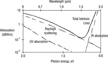
Intrinsic Absorption As the name suggests, it is mainly caused by the interaction with major components of the fiber material. Two factors cause intrinsic losses – Material resonances in UV and IR regions, and Rayleigh scattering. Silica displays heavy absorption in the UV and IR regions and is wavelength-dependent. Rayleigh scattering occurs because the EM field excites the irregularities of the molecules of SiO2. Essentially, there are three factors that contribute to the intrinsic absorption in optical fibers: ultraviolet absorption, infrared absorption, and ion resonance absorption.
- Ultraviolet absorption. Ultraviolet absorption is caused by valence electrons in the silica material from which fibers are manufactured. Light ionizes the valence electrons into conduction. The ionization contributes to the transmission losses of the fiber.
- Infrared absorption. Infrared absorption occurs due to the absorption of photons by the atoms of the glass core molecules. The absorbed photons are converted to random mechanical vibrations typical of heating.
- Ion resonance absorption. During the manufacturing of optical fiber cables, water molecules may get trapped in the glass process. This results in OH– ions in the material, which cause ion resonance absorption. Iron, copper, and chromium molecules also cause ion resonance absorption.
The figure below shows typical absorption losses in optical fiber cables due to ultraviolet, infrared, and ion resonance absorption.

Extrinsic Absorption Contrary to intrinsic absorption, extrinsic absorption is caused by different types of impurities usually contained within the fiber material (i.e. the glass). Common metallic ion impurities in glasses are Cr3+, Cu2+, Fe2+, Fe3+, Ni2+, Mn3+, which absorb light energy strongly in the wavelength range of 600–1600 nm. Another source of extrinsic absorption is the presence of hydroxyl ions, OH-. These molecules enter the silica in the form of water vapor during the manufacturing process.
The figure below shows attenuation (dB/km) versus photon energy (eV) as well as wavelength.
Scattering Transmission Losses
Scattering loss occurs due to transfer of the optical power available within one guided propagation mode into a different mode of propagation. The scattering may happen when a light beam propagating within the fiber strikes at an imperfection in a core material and then changes its direction. This scattering effect prevents attainment of desired total internal reflection at the intersection of the fiber core and the cladding. This may result in a power loss. Even very minute variation in the specified value of the core refractive index can be considered as an optical obstacle by a propagating light beam.
Linear Scattering Losses
Rayleigh scattering and Mie scattering are examples of linear scattering mechanisms.
1. Rayleigh scattering. It is the prominent intrinsic loss mechanism which occurs because of core refractive index fluctuations due to density and compositional variations in the glass lattice on cooling. During manufacturing of optical fibers, glass is drawn into long fibers of very small diameter. During this process, the glass is in a plastic state (not liquid and not solid). The tension applied to the glass causes the cooling glass to develop permanent submicroscopic irregularities.
When light rays propagating down a fiber strike one of these impurities, they are diffracted. Diffraction causes the light to disperse or spread out in many directions. Some of the diffracted light continues down the fiber, and some of it escapes through the cladding. The light rays that escape represent a loss in light power.
2. Mie Scattering. Scattering of light that occurs because of the presence of some imperfections in the waveguide structure is known as Mie scattering. It can result into considerable attenuation in optical fiber. It may occur due to the following factors:
- non-perfect cylindrical structure of waveguide
- irregular surface of the core-cladding interface
- difference in refractive indexes of the fiber core and cladding along the length of the fiber
- fluctuations in the fiber core diameter
- presence of strains and bubbles in the fiber
When the dimension of the scattering inhomogeneity exceeds λ/10, then the effect of Mie scattering may be very large, mainly in the forward direction. Mie scattering can cause significant losses in fiber, depending upon the fiber material, design and manufacturing process.
Non-Linear Scattering Losses
In general, a non-linear optical effect is one when its parameters are functions of optical signal intensity. Non-linear scattering is also called stimulated scattering when light power essentially increases. Stimulated scattering means transfer of light energy from the incident wave to scattered wave at longer wavelength, with the small energy difference being released in the form of phonons.
A phonon is an elementary particle analogous to a photon but differs from a photon in its quantum properties. Scattered optical waves are also known as Stokes’ optical waves. Stimulated scattering increases fiber losses at a high level of transmitted optical power (negligible at low power levels).
Stimulated scattering is characterized by three major parameters, namely,
- Threshold power. It is the power of incident light at which loss due to stimulated scattering is 3 dB over fiber length L. The intensity of scattered light goes exponentially when the power of incident light exceeds threshold power.
- Gain coefficient. It refers to peak gain of stimulated scattering at given l.
- Spectral Bandwidth. Range of frequencies within which scattering is effective.
Bending Transmission Losses
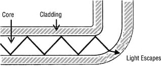
Bending an optical fiber too sharply can increase fiber losses by causing some of the light to meet the intersection to the fiber core and the cladding at less than the critical angle of incidence, thereby preventing the desired phenomenon of total internal reflection. The figure below shows how this can happen.
Losses vary greatly with the type of fiber. For example,
- Plastic fiber may have losses of several hundred decibels per kilometer.
- Graded-index multimode glass fiber has attenuation figure of about 2–4 dB/km, while single-mode glass fiber has attenuation figure of about 0.4 dB/km or less.
Definition of microbend: It is a minor geometric imperfection present along the fiber axis that actually represents a discontinuity at which Rayleigh scattering can occur.
- Microbends may occur due to differences in the thermal contraction rates for the materials used for the fabrication of the fiber core and the cladding.
- Microbends, sometimes called constant-radius bends, result in radiation losses in the fiber.
Microbends may also refer to some imperfections in the geometry of the interface boundary between the fiber core and the cladding, as shown in the figure below.
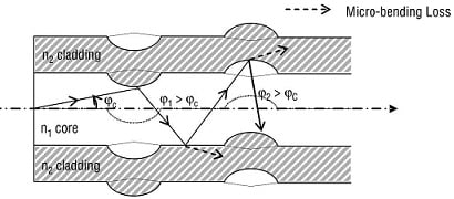
The beam, which initially travels at the critical propagation angle, after being reflected at these imperfection points, will change the angle of propagation. This results in partial refraction and will leak out of the core, which is called microbending loss. The condition of total internal reflections will not be met at microbends.
Coupling Transmission Losses
In optical fiber cables, coupling losses can occur at any of the following three types of optical junctions:
- connections between light source and the fiber at the transmitter end (source-to-fiber power launching)
- fiber-to-fiber interconnections (to extend the length of the optical fibers)
- connections between the fiber and the photodetector at the receiver end
Coupling the fiber to sources and detectors creates losses, especially when it involves mismatches in numerical aperture or in the size of optical fibers.
In an optical fiber communication system, the losses in splices and connectors can easily be more than in the fiber cable itself. Coupling losses are normally caused by the imperfect physical connections in optical fiber communication system. Junction losses are most often caused by one of the following alignment problems:
- lateral or axial misalignment
- gap misalignment
- angular misalignment
- imperfect surface finishes
1. Lateral or axial misalignment. Lateral or axial misalignment or displacement is the lateral or axial displacement between two pieces of adjoining fiber cables. The figure below shows lateral misalignment in optical fibers.
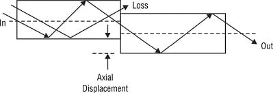
The amount of coupling loss may vary from a tenths of a dB to several dBs. This loss is generally negligible if the fiber axes are aligned to within 5% of the smaller fiber’s diameter.
2. Gap misalignment. Gap misalignment or displacement occurs when splices are made in optical fibers, and the optical fibers should actually touch. If the fibers are kept far apart, there will be more loss of optical signal. The figure below shows gap misalignment in optical fibers.
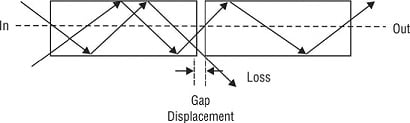
If two fibers are joined with a connector, the ends should not touch because the two ends rubbing against each other in the connector could cause damage to either or both fibers.
3. Angular misalignment. Angular misalignment or displacement is shown in figure below.
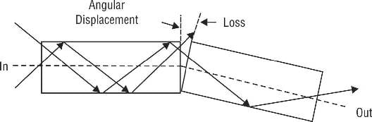
If the angular displacement is less than 2°, the loss will typically be less than 0.5 dB.
4. Imperfect surface finish. Imperfect surface finish is shown in figure below.

If the fiber ends are less than 3° off from perpendicular, the losses will typically be less than 0.5 dB. The ends of the two adjoining fibers should be highly polished and fit together squarely.

