
PLUMBICON CAMERA TUBE
The plumbicon camera tube is developed by Philips in 1963 to remove the problem of image lag in vidicon. It has a photoconductive target plate of lead mono-oxide (PbO) sand-witched between an n-type and p-type layer. The name of this tube is derived from the lead i.e. plumbicon or Pb, which is used as target material in plumbicon camera tube.
Table of Contents
Construction of Plumbicon camera tube
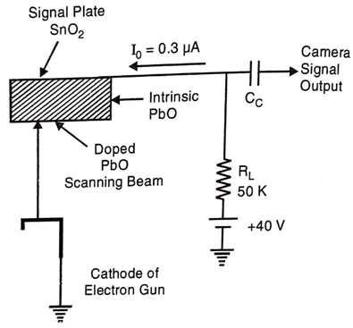
The construction of plumbicon is very similar to the standard vidicon except the target. In this also focus and deflections are achieved by magnetically. This tube consists of a glass envelope with an optically flat faceplate. The faceplate operates effectively as a P-I-N semiconductor diode. The inner surface of the faceplate is coated with a thin layer of tin oxide (SnO2) which is transparent to light and a good conductor of electricity. This forms an N-type layer and acts as the signal plate. It is connected to load through a metallic ring around the tube.

On the scanning side, a layer is deposited a photo-conductive layer of pure lead mono-oxide (PbO) which is intrinsic or I-type and is a good conductor and has a large number of free electrons. Finally, the pure PbO is doped to form a P-type semiconductor on which the scanning beams bands. Thus the target in plumbicon becomes a PIN diode. The thickness of the target plate is about 15 mm. Details of the target plate are shown below.
Working of Plumbicon camera tube
The scanning of the target is being done by a sharply focused electron beam produced by an electron gun. The electron gun consists of an indirectly heated cathode, control grid (G1) and accelerating grid (G2). Focusing is achieved by applying both electrostatically by (G3) and magnetically by an eternal focus coil. Grid (G3) at 260V is at lower potential with respect to the accelerating grid (G2 at 300V) and hence slows down the electrons. The magnetic focusing converges the electrons to the center of the beam and resulting in a sharp spot on the target. A fine wire mesh grid (G4) is connected to 400V and acts as a muzzle for the electron gun. The target is kept at 40V, which allows the electrons to land at the target with almost zero velocity and perpendicular to the target.

When the light incidents on the target, electrons are released. In the intrinsic layer, the electric field gradient setup is very high and due to this high gradient, all released electrons sweep the target quickly so that there is no image lag.
The PIN diode acts as a capacitor and the free electron released by light causes a resistance to be formed across the capacitance.
The conductive film of thin oxide (SnO3) is connected to the target supply of 40V through a load resistance RL to develop the camera output signal voltage. The light is focused through the transparent layer of tin oxide on the photoconductive lead mono-oxide. The targets prevent conductions in the absence of light because of the absence of any charge carriers. Hence there is almost nil dark current i.e. approximately 4 x 10⁻⁹ Amp. Because of the incident light, photo excitations of semiconductor junction occurs. Depending on the intensity of light the value of resistance varies and hence the flow of signal current. As the light intensity increases the resistance decreases and the flow of current signal increases. The current is proportional to the incident light on each photo element. The video signal is developed across the load resistance.
Light Transfer Characteristics
- The response of the output current and target illumination of a plumbicon is shown in the Figure below.
- This curve is a straight line with a higher slope as compared to the response curve of a vidicon camera tube.
- Due to the less recombination of photogenerated electrons and holes in the intrinsic layer, hence output current is high. So, its sensitivity is higher.
- In case when the target voltage is higher than 20V, then the tube operates in photo saturated mode.
- The spectral response of the plumbicon is closer to that of the human eye except in the red colour region.
- The lead oxide target reflects red light towards the face light and rest all colours are absorbed.
- This red light is again reflected by the faceplate towards the target. Due to these reflections a red halo around a white spot the scene.
- This red halo can be eliminated by an anti-halo disc whose circumference is coated black to absorb the reflected light as shown in the figure.

Characteristics of Plumbicon Camera Tube
- Signal to Noise Ratio: 47 dB
- The sensitivity of plumbicon is about 400 µA/lumen
- Image lag is almost negligible.
- Halo Effect occurs.
- The dark current is less than 1 nA.
- IR sensitivity is moderate.
- The resolution is about 50% at 400 lines.
Advantages of Plumbicon Camera Tube
- Signal to noise ratio is less as compare to vidicon camera tube.
- Sensitivity is much batter rather than vidicon camera tube.
- Image lag is negligible.
- Absence of ghost image.
- Dark current is very less.
- Characteristics curve is linear.
- Very small in size as compared to image orthicon.
- Resolution is 50% at 400 lines.
Disadvantages
- Halo effect occurs and therefore an antihalo disc is used.
- Its sensitivity is less than that of image orthicon.
- Spectral response is poor in red.
- Size is bigger than vidicon.
- Needs Gamma correction.
- Resolution is poor than vidicon.
Application
- Indoor and outdoor shooting.
- Suited to colour TV due to absence of image lag.

