Table of Contents
Delta Gun Color Picture Tube
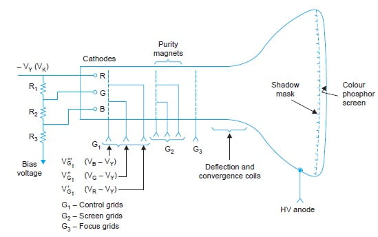
Delta Gun color picture tubes employ three separate Guns, equally spaced at 120 degrees with respect to each other, generates three high velocity (25 kV acceleration) electrons beams. They are mounted on the corners of an equilateral triangle, forming the Greek letter delta (D) that is why the tube has been named Delta Gun picture tubes. The guns are slightly tilted inwards to the tube axis to make the beam converge near the faceplate. BR & G represents guns for video signals pertaining to blue, red, and green colors, respectively as shown in the figure below.

Each gun in the three gun delta picture tube has its own separate set of cathode, control grid, accelerating grid and focus grid so that individual color signals can be coupled to the grid cathode circuit to modulate beam intensity.
Shadow Mask
On the screen, there are about one million dots of phosphor in groups of three, corresponding to red, green, and blue light. These are deposited on the back of the faceplate. Each group is called Triads. Thus there are 333000 triads.
Each dot is of a 0.42 mm diameter with a spacing of 0.72 mm between the respective dots of the adjacent triads.

A thin perforated metal sheet is placed about one cm behind the tube scren, to ensure the correct landing of beam on phosphor, is known as Shadow mask. It is supported by a heavy internal frame for rigidity.
The mask has one conical hole for every phosphor dot triad on the screen as shown in above figure. The hole is conical to prevent emission of secondary electrons. Shadow mask is used to ensure that the beams land on the correct phosphor.
Three electron beams converge on a hole of the mask, and from there they diverge to strike the respective dots of triads. The shadow mask s blocks an appreciable portion of the beam current dissipating several watts of Power.
The transparency of the shadow mask is only 20%. The remaining 80% of the total beam current energy is dissipated as heat loss in the shadow mask. This is why color picture tubes use higher anode voltage and need larger beam currents and cathode currents than monochrome tubes.
Phosphor used for color tubes are :
- Red: Zinc sulfide
- Green: Zinc silicate
- Blue: Europium and yttrium
- Persistency: 1 ms
Space between the phosphor dots filled with black pigments to improve the contrast by absorbing ambient light.
All three color difference signals are then fed to the three grids of the color picture tubes.
The inverted luminance signal (-Y) is applied at the junction of the three cathodes
Principle of Working
The overall color screen is determined by the intensity of each beam and the phosphors. The arrangement of the Delta gun picture tubes is shown in figure below.
The inverted luminance signal (-Y) is applied at the junction of the three cathodes. The signal voltage subtracts from each other to develop control voltages for the three electron guns.

The electron beams from the three electron guns strike three phosphor dots of red, green, and blue (R, G, and B primary colors) phosphor in a triad glow simultaneously. The intensity of the glow is proportional to the intensity of the video signal of the respective color.
The eye integrates the three colors emitted by the phosphor dots at a time and perceives the resultant color of the concerned pixel as in the original picture. Triads glow one after another in quick succession due to deflection of the beams and thus the whole picture is reproduced in its original forms.
In the absence of two-electron beams, dots of only one color phosphor get excited and raster will have only one of the primary colors. In case when all the three electron beams are off than the picture will be black in color.
If the amplitude of color difference signal drops to zero, the only Y signal control the three guns and a monochrome picture is produced on the screen.
V_{G1}^{'}-V_{k}=(V_{R}-V_{Y})-(-V_{Y})=V_{R} V_{G1}^{''}-V_{k}=(V_{G}-V_{Y})-(-V_{Y})=V_{G} V_{G1}^{'''}-V_{k}=(V_{B}-V_{Y})-(-V_{Y})=V_{B}Purity and Conversance
- While deflecting the three beams by vertical and horizontal deflecting coils it necessary to ensure that each produces a pure color and all the three color raster overlap each other.
- For obtaining purity in color each beam should land at the center of the corresponding phosphor dot irrespective of the location of the beam on the raster.
- This needs precise alignment of the color beams and is carried out by a circular magnet assembly known as the purity magnet.
- Purity magnets mount on the neck of the tube and close to the deflection yoke.
Yoke Position
The position of the yoke on the tube neck determines the location of the deflection center of the electron beams. A wrong setting will result in poor purity due to improper entry angles of the beam into the mask opening.
Convergence
The technique of bringing the beams together so that they hit the same part of the screen at the same time to produce three coincident rasters is referred to as convergence.
Convergence errors are caused by:
- Non-coincident convergence plane
- Non-uniformity of the deflection field.
- The flat surface of the picture screen.

Static and Dynamic convergence
Static convergence: It involves movement of the beam by permanent magnetic fields, one correctly set; bring the beam into convergence in the central area of the screen. The permanent ring magnets are adjusted for static convergence in the central area of the screen.
Dynamic convergence: Apart from the static convergence at the center it is necessary, to ensure dynamic convergence when the beams are deflected to form a raster. Dynamic convergence over the rest of the screen is achieved by continuously varying (dynamic) magnetic field.
Pin-cushion Effect
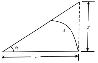
We know that the screen of a picture tube is rectangular, it is not circular, and the magnetic deflection would not be uniform. The distance of corners is more as compared to the center point. Deflections of electron beam under a magnetic field along the circular arc and on a rectangular surface are illustrated in the figure below.

We get
d = L.θ = L sin θ
where
- d = Length of the arc
- L = Distance from the center of a circular screen
- θ = deflection angles in radians
Practically for the rectangular screen, the same deflection angle θ will have to move the beam to longer distance d and that will be equal to L tan θ. This causes the raster to be stretched at the corners and the shape of the raster is shown below.

Dynamic pincushion correction is used with color picture tubes. Such a correction automatically increases horizontal width and vertical size in those regions of the rater that are shrunken because of pincushion distortion.
Degaussing
Degaussing means demagnetizing iron and steel parts of the picture tube mounting. The main cause of poor purity is the susceptibility of the mask and its mounting frame to become magnetized by the earth’s magnetic field and/or by another strong magnetic field. The effects of that localized magnetic field are the deviation of electrons beams from their normal path. To prevent such effect the picture is magnetically shielded. It is done by placing thin silicon steel housing around the belly of the tube.
Drawbacks of Delta Gun Tubes
- As the beams are not in the same line, the focus is not sharp all over the screen.
- Electron’s transparency of the shadow mask is very low i.e. 20%. Thus 80% of the beams are stopped from striking the phosphor dots, resulting in poor efficiency.
- The convergence of the three beams on the respective dots is difficult. It required 4 static and one dynamic convergent magnets assembly, resulting in 12 preset controls.
These tubes are not used and are being replaced by PIL and Trinitron picture tube.
Related Posts:


