
Table of Contents
What is Diode?
In electronic gadgets, a diode is a two-terminal electronic segment that transmits electric flow in just a single direction. The term semiconductor or PN junction diode is mostly used. This is a crystalline bit of semiconductor material associated with two electrical terminals. A vacuum tube diode (presently minimal utilized aside from in some powerful advances) is a vacuum tube with two anodes: a plate and a cathode.
The most widely recognized capacity of a diode is to enable an electric current flow to go one way (called the diode’s forward direction), while at the same time blocking flow the current in another way (the reverse direction). Hence, the diode can be thought of as an electronic adaptation of a check valve. This unidirectional conduct of current is known as rectification, which is utilized to change alternating current (AC) to direct current (DC). This rectification is very useful in electronic circuits because most of the circuits are used on direct current.
But, diodes can have more complex behavior on use in the circuit than the basic on-off activity. This complexity is due to non-linear electrical attributes, which can be custom-made by shifting the development of their P-N intersection. To overcome this complexity some special purpose diodes were made. They can perform many different functions.
Some examples are,
- The specific diode which used to regulate voltage (Zener diodes)
- For electronically tune radio and TV receivers (varactor diodes)
- To create radio frequency (tunnel diodes)
- To generate light (light-emitting diodes)
- Tunnel diode shows negative resistance, which makes them helpful in a few kinds of circuits.
History
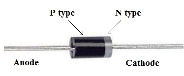
The diode was the first implementation of semiconductor materials. The crystals’ rectifying abilities of diode was firstly introduced by German physicist Ferdinand Braun in 1874 to the world. Around 1906 cat’s whisker diodes developed, which made of mineral crystals such as galena, was the first semiconductor diode. Today most diodes are made of silicon, yet different semiconductors, for example, germanium are utilized for a diode, the terminals are unique and it is important how you interface the diode in the circuit. So you need to identify the anode (+) and the cathode(-) terminals. To identify the terminal of diode the digital multimeter (DMM) is very useful but on the packaging of diode it is marked that which terminal is anode or which is cathode. The diode allows current to flow into the anode (+), just like current flows into the higher voltage side of the resistor.
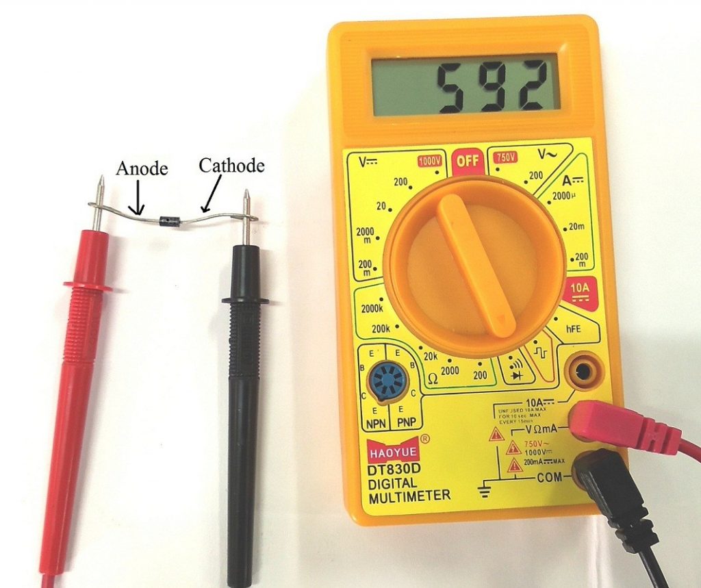
Testing the polarity of diode with DMM
If the display of DMM is show low resistance it means the diode is in forward biasing. This low resistance shows that the terminal which connected to the positive terminal or red wire of multimeter is the anode. Another terminal which connected to negative terminal or black wire of multimeter is the cathode.
If the display of DMM is showing high resistance it means the diode is in reverse biasing. This high resistance terminal which connected to the positive terminal or red wire of multimeter is the cathode. Another terminal which connected to negative terminal or black wire of multimeter is the anode.
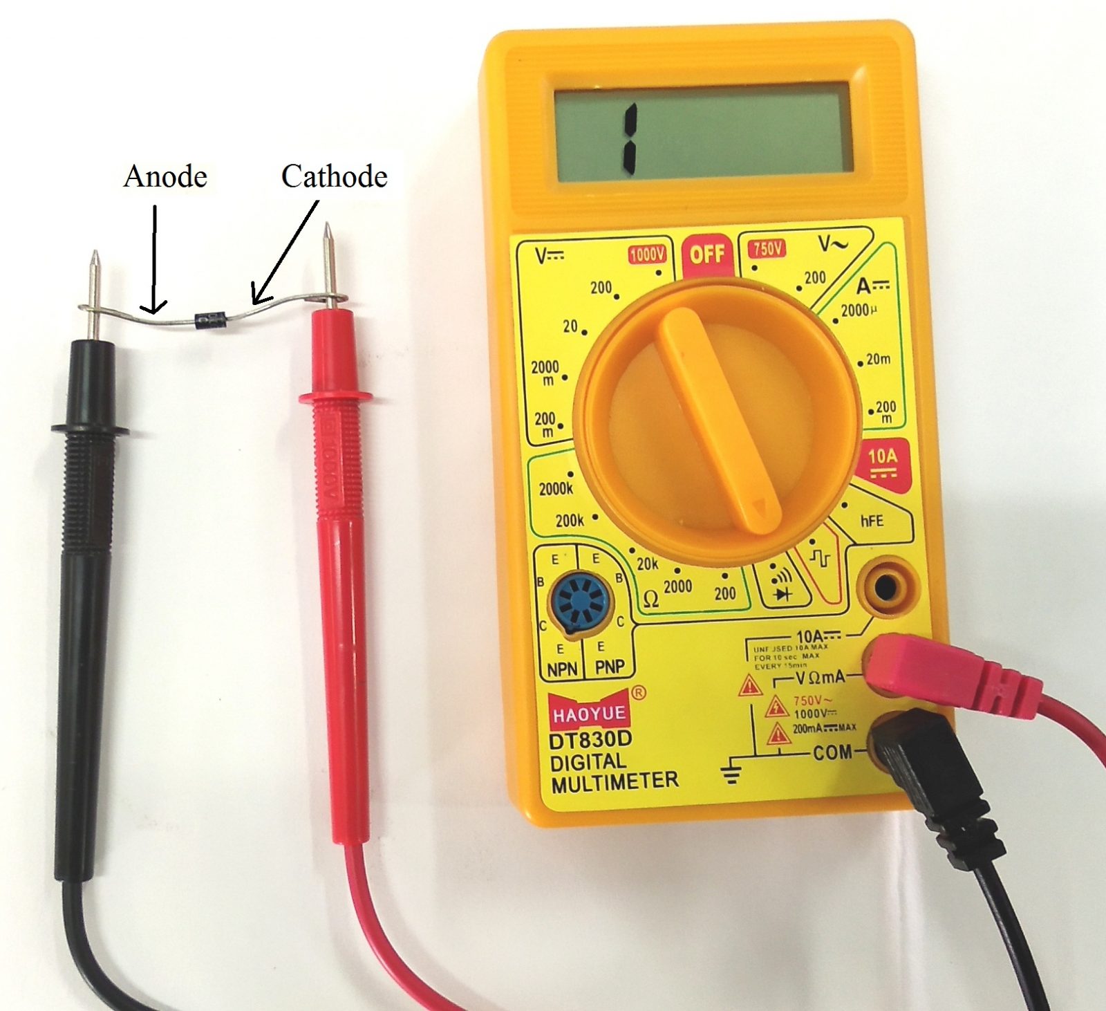
Note – If the diode is short then multimeter shows zero ohm resistance on display, then check diode on continuity point and check if diode was short then multimeter sound a continues to beep.

