Table of Contents
Waveguide Attenuator
Waveguide Attenuator: An attenuator is a passive device that is used to reduce the strength or amplitude of a signal. At microwave frequencies, the attenuators were not only meant to do this, but also meant to maintain the characteristic impedance (Z0) of the system. If the Z0 of the transmission line is not maintained, the attenuator would be seen as impedance discontinuity, which causes reflections. Usually, a microwave attenuator controls the flow of microwave power by absorbing it.
Attenuation in dB of a device is ten times the logarithmic ratio of power flowing into the device (Pi) to the power flowing out of the device (Po) when both the input and output circuits are matched.
Attenuation in dB=10\log_{10}\frac{P_{i}}{P_{0}}
Principle of Waveguide Attenuator
In a microwave transmission system, the microwave power transferring from one section to another section can be controlled by a device known as microwave attenuator. These attenuators operate on the principle of interfering with electric or magnetic or both the fields. A resistive material placed in parallel to electric field lines (of field current) will induce a current in the material,which will result in I2R loss. Thus, attenuation occurs by heating of the resistive element.
Attenuators may be of three types:
- Fixed
- Mechanically or electronically variable
- Series of fixed steps
Fixed Attenuators
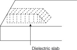
Fixed attenuators are used where a fixed amount of attenuation is needed. They also called pads. In this type of attenuator tapering is provided by placing a short section of a waveguide with an attached tapered plug of absorbing material at the end. The purpose of tapering is for the gradual transition of microwave power from the waveguide medium to the absorbing medium. Because of the absorbing medium, reflections at the media interface will be minimized. In a fixed attenuator, plug is nothing but a dielectric slab which has a glass slab with aquadog or a carbon film coating. The pad is placed in such a way that the plane is parallel to the electric field. For this, two thin metal rods are used.

The amount of attenuation provided by the fixed attenuator depends on the strength of the dielectric material, the location and area of the pad, type of material used for pad within waveguide and the frequency of operation.
Variable Attenuators
For providing continuous or stepwise attenuation variable attenuators are used. The provided attenuation depends on the insertion depth of the absorbing plate into the waveguide. The maximum attenuation will be achieved when the pad extends totally into the waveguide. This type of variable attenuation is provided by knob and gear assembly which can be properly calibrated. The power transmitted to the load can be varied manually or electronically from nearly the full power of the source to as little as a millionth of a percent of the source power depending on the frequency of operation. The types of variable attenuators are
- Flap or resistive card-type attenuators
- Slide vane attenuators
- Rotary vane attenuators
Resistive card (flap type) and slide vane attenuators
Mechanically, variable attenuators are stepwise variable attenuators. Examples are flap type, slide vane type attenuators as shown in figure below. In contrast, electronically variable attenuators are continuously variable attenuators. They are used for various applications like requiring automatic signal leveling and control, amplitude modulation, remote signal control, and so on.
A simple form of an attenuator consists of a thin, tapered resistive card, whose depth of penetration into the waveguide is adjustable as shown below. The card is inserted into the waveguide through a longitudinal slot cut in the center of the broad wall of a rectangular waveguide.

The Slid Vane or adjustable disk attenuator is showm in figure below. In this attenuator, the vane is positioned at the center of the waveguide and can be moved laterally from the center, where it provides maximum attenuation to the edges. However, the attenuation is reduced at the edges, as the electric field lines are always concentrated at the center of the waveguide.
The vane is tapered at both the ends for matching the attenuator with the waveguide. An adequate match is obtained if the taper length is made equal to λ/2. The biggest disadvantage with these attenuators is that their attenuation is frequency sensitive, and also, the phase of the output signal is a function of attenuation.

Rotary Vane Attenuators
The most satisfactory precision attenuator is the rotary vane attenuator. The structure of this attenuator is shown in figure below. It consists of two rectangular to circular waveguide tapered transitions, along with an intermediate section of a circular waveguide that is free to rotate. All the three sections contain thin resistive cards.
The input signal passes the first card with a negligible attenuation, because the electric field of the TE10 wave mode is perpendicular to the card. Then, the wave enters through a transition to the circular waveguide. The attenuation is adjusted by rotating the circular waveguide section and the resistive card within it. The field of the TE11 wave mode can be divided into two components: one perpendicular to the card and the other parallel to it. The latter component is absorbed by the card; the former component enters the output of the waveguide, in which again its component parallel to the resistive card is absorbed.

The plates are usually thin with εr > 1, μr = 1, and conductivity σ of a finite nonzero value. The plates attenuate the wave that is travelling, and the amount of attenuation is dependent on the properties of the material from which the plate is made, the dimensions of the slab, and the angle between the electric field at the input and the plane of the resistive card in the circular section. The attenuation in decibels is given by
Attenuation in dB = −40 log (cos θ) dB
where θ is the angle between the electric field at the input and the plane of the resistive card in the circular section. Hence, the attenuation is controlled by the rotation of the center section. Minimum attenuation at θ = 0°, and maximum attenuation at θ = 90°. The attenuation provided by this device depends only on the rotation angle θ but not on the frequency. This device is very accurate, and is, hence, being used as a calibration standard. Its accuracy is limited only by imperfect matching and by misalignment of the resistive cards.
Related Posts:

