This post is all about the transistor and its testing with a multimeter.
Table of Contents
Transistor
The transistor is a two PN diodes back to back combination where P-type or N-type semiconductor sandwich between another type of semiconductor material. Mainly there is two types of transistors, NPN and PNP, with different circuit symbols. The letters of transistors (PNP & NPN) refers to the layers of P-type or N-type semiconductor material used to form the transistor.
NPN transistors are mostly used these days because it is the easiest type to make from silicon type semiconductor material. This post is mostly related to identifying the terminals of NPN transistors. If you don’t know about it then it is best to start by learning how to identify them first. The NPN transistor has three legs which are labeled as emitter (E), base (B) and collector (C). NPN transistors is a Bipolar Junction Transistor (BJT). In which two layers of N-type semiconductor are present and both are separated by a thin layer of P-type semiconductor. In this transistor majority, charge carriers are electrons and minority charge carriers are holes.

Similarly, PNP transistor is also a BJT. In this transistor N-type semiconductor sandwich between two P-type semiconductors. In PNP majority charge carriers are holes and minority charge carriers are electrons.
There are so many methods of identifying the terminals of transistors but we discuss only one method, which is done with the help of multimeter.
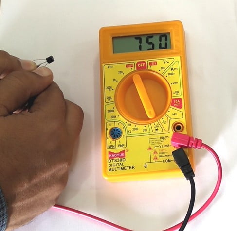
Testing of NPN transistor with Digital Multimeter
In the Digital Multi-Meters (DMM’s) there is a diode test point or continuity point. The symbol of this point is something like a diode (picture the greater than sign as a black triangle pointing to and touching the black line). Firstly you should know about a good transistor, so you’ll be able to tell if you have any bad transistor.

Steps of testing transistor
- First of all, ensure that the transistor which will test is out of a circuit.
- Now insert the red lead plug into the “V” socket of the millimeters and the black lead plug into the “COM” socket.
- Set the Digital Multimeter at the diode testing point of continuity point.
- Now connect the positive or red and negative or black probes to any two leads of the transistor until we get a reading on the screen of multimeter other than infinity.
- When we will get a reading other than infinity, leave one of the probes on one of the legs of the transistor (it doesn’t issue which one).
- Now connect the other probe to the third leg of the transistor. If the next reading will other than infinity then repeat step 4.
- Now leave the other probe on the leg of the transistor which as connected previously, when we got the reading other than infinity.
- After that take the other probe and connect to the third leg, then reading will other than infinity shown on the screen.
- The same infinity is shown on screen, then repeat 3-6, but start with 2 different leads, until we can leave 1 leg in place and get a reading other than infinity on the other 2 legs.
- If we kept the positive probe at the center leg of the transistor then it is an NPN transistor. If we kept the negative probe at the center leg then we have a PNP transistor.

- The center leg of the transistor is called Base.
- When we exchange, the testing probes-
- The leg with the lower reading of resistance is the Collector
- The legs with the higher reading of resistance is the Emitter.