Table of Contents
Attitude and Orbit Control System (AOCS)
Attitude and orbit control system is used to control the orbit of the satellite, besides helping to maintain stabilization and its position. The control can be affected by the satellite itself and from the ground. Attitude and Orbit Control System (AOCS) consists of four major parts:
- Sensors
- Propulsion system
- Attitude control
- Orbit control
Forces Acting on a Satellite
There are a number of forces working on a satellite which tend to change attitude and orbit of a satellite beyond the permissible limit. These forces are :
- Asymmetry of the earth’s gravitational field: Earth is not a true sphere. It is bulging at the equator by about 65 km at the longitudes of 165oE and 15oW. This causes an acceleration and hence for accurate positioning, the satellite must be accelerated in the opposite direction by firing the rocket motors called thrusters at appropriate intervals. Earth is flattered at the poles by about 20 km but this has little effect on a geostationary satellite.
- Gravitation due to sun, planets and moon: They set up rotational moments if the satellite is not perfectly balanced. Moon being the nearest heavy mass, has maximum effect.
- Pressure due to solar radiation: It can also change orientation (spin-axis) of the satellite.
- Magnetic field of the earth: It can exert forces on the satellite if a net magnetic moment is present, thus affecting its velocity and orientation.
Need of Attitude and Orbit Control
Change in the spin axis of the satellite will cause pointing error between the satellites antenna and the earth station’s antenna. This will reduce the signal at the receiving side and will degrade C/N ratio. Hence the need of maintenance of correct attitude. As the extra forces can change velocity of the satellite and therefore angle of inclination of the orbital plane with respect to the equitorial plane, the satellite will become non-geostationary. This will require steering of the earth station antenna to get the best signal from the satellite. Thus correct attitude and correct orbit are essential requirements for the optimized performance of the satellite links.
Sensors
For attitude control, two types of sensors are used in the satellite:
- Earth sensor
- Sun sensor
Earth Sensor
It is a passive infrared device, operating in 14-16 µm wavelength. It senses the infrared rays coming from around the horizon. There is a sharp temperature difference between the space and the earth’s horizon, as space is cool and earth is warm. Two earth sensors are used, positioned 5° north and 5° south of the spin axis. When the spin axis of the satellite is correctly maintained the output of north and south sensors are in phase, otherwise they are out of phase. The phase difference pulses are sent to the earth station and they measure earth aspect angle.
Sun Sensors
It has a fan shaped field of view. It operates in the visible spectrum and uses a photocell for detecting solar radiations. There are two solar sensors, one parallel to the spin axis and the other canted 35°. Pulses from the sun sensors are sent to the earth station to determine solar aspect angle.
Data from the earth and sun sensors is analyzed and orientation of the satellite is accurately determined by the computers at the earth’s station. Command are generated and sent to the satellite to fire the rocket motor for correcting the axis.
Propulsion System
It is the reaction control system carried by the satellite in the geostationary orbit so as to generate forces on it whenever required. The reaction control system has a supply of fuel and it helps the satellite to move, to its assigned position in orbit, to maintain it in that position and to maintain the direction of spin axis attitude control in the case of forces that perturb it. Usually a propulsion system consists of 3 units:
- Low thrust actuators: Devoted to attitude and orbit corrections that provide an annual velocity increment of the order of 50 m/s.
- High thrust motor: Which provides the velocity increment required for the geostationary orbit injection at the transfer orbit apogee.
- With space shuttle launched satellites: It provides the velocity increment required to inject the satellite into the transfer orbit.
Out of these three propulsion units the low thrust actuators are of much importance for geostationary orbit because it is responsible for keeping the satellite in its orbit with its perfect attitude till its life end. The low thrust actuators can be either chemical ones or the electrical ones.
The chemical thrusters have a thrust level of between 0.5 N and few 10000 N. In chemical thrusters gases are generated at high temperatures by chermeal reaction of propellents which may be either solid or liquid. The gases are then accelerated by a nozzle.
The electric thrusters produce a thrust only in between 2 and 10 mN. They provide thrust by accelerating ionized mass in an electromagnetic or electrostatic field. In communication satellites chemical thrusters are used.
Attitude Control System
The attitude control of a spacecraft is necessary so the antennas must be pointed correctly at the earth. Gravitational forces from the sun, moon and planets will setup rotational moments when the spacecraft is not perfectly balanced. These are carried out by control loops based on error detection and decision systems as shown in figure below.

They use the telemetry, tracking, and command (TT&C) subsystems for information exchange between satellite and earth. The attitude control may be:
- Passive
- Active
In passive attitude control the required attitude corresponds to a position of a satellite, while for active attitude control the satellite is unstable or sufficiently stable within the desired attitude configurations. Mainly four oprations are requered for this:
- Detection of the satellite attitude
- Comparison with the reference axis
- Determination of the corrective torque.
- Correction of the altitude by actuators mounted on the satellite.
Any spacecraft is governed using three axis:
- Yaw
- Roll
- Pitch
Satellite Stabilization
In order to control the attitude in space. the satellite has to be propely oriented using momentum wheels and thruster motors in these three axis. The two major methods used are:
- Spin stabilization.
- Three axis body stabilization.
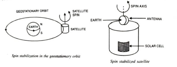
Spin Stabilization
It is the most commonly employed method where the entire spacecraft is rotated at 30 to 100 rotations per minute. This spin provides a powerful gyroscopic action to maintain the spin axis in the correct direction. Such satellites consist of cylindrical drum covered by solar cells and the rocket motors. The transponder is mounted on the top of the drum. It is driven by an electric motor in the appropriate direction tothat of the drum, so that the antennas remain pointing towards the earth. This opposite motion is called despun. The despun section is kept stationary by counter rotation provided is by small gas jets mounted on the periphery of the drum. Figure shows the spin stabilization in the geostationary orbit. Spin stabilized satellites are mainly the communication satellites.
Three Axis Body Stabilization
On the other hand, a satellite can rotate about the three axis termed as yaw, roll and pitch axis. When a statellite is stabilized about these axis, it is called three axis body stabilization.
In this method, stability is achieved by mounting three momentum wheels on three mutually perpendicular axis as shown in the figure below.

A momentum wheel is a high speed wheel driven by a motor. It is kept in a sealed evaluated chamber. Increase in its speed increases the angular momentum. Change in the attitude are transmitted to the earth station by telemetring the data from the sensors. The data is analysed and commands are sent to the satellite to increase or decrease the speed of the momentum wheels as per requirement to correct the attitude about its three aixs: role axis (the orbital plane), pitch axis (normal to the orbital plane) and yaw axis (the local vertical plane facing the earth station). Antennas are mounted on the satellites surface facing the earth.
Orbit Control System
A GEO satellite is subjected to several forces that tend to accelerate it away from its required orbit. It is the function of the orbit control system to return it to its correct orbit.
For orbit control, sensors are used in the satellite to measure linear acceleration (momentum mentum wheels cannot be used for this control because they cause rotational torques), changes in velocity, sensed by the velocity sensors, are transmitted to the earth’s controlling station. These changes are analysed and, appropriate commands are generated and sent to the satellite for correcting the velocity.
To correct change in the inclination angle (i), change of velocity at right angles to the orbital plane is needed. This correction requires more fule than for any other correction. A typical satellite weighing 1000 kg may need 30 kg of fuel to maintain inclination within ±0.1°. This puts a penality by reduction in the communication payload and therefore reduction in satellite’s capacity. Hence in most of the satellite systems, inclination control is not used. Instead, the satellite is launched with an initial inclination of about 3°. It will be reduced by 0.85° per year due to forces working on the satellite. Thus after three or four years, the orbit would be in the equatorial plane. With earth stations having steerable antennas, drift in inclination can be managed by proper tracking, and saving in fuel can be used to carry more transponders.

