Table of Contents
Algorithmic State Machine
The Algorithmic State Machine (ASM) method is a method for designing finite state machines. It is used to represent diagrams of digital integrated circuits. The ASM diagram is like a state diagram but less formal and this easier to understand.
The conventional flowchart is a sequential way of representing procedural steps and decision paths for algorithms and no time relations are incorporated. While ASM chart is a representation of a sequence of events together with timing relations between states of sequential controller and events occurring while moving between steps.
An Algorithmic State Machine (ASM) diagram offers several advantages over conventional state diagrams.
- For larger state diagrams, ASM diagrams are easier to interpret.
- Conditions for a proper state diagram are automatically satisfied.
- ASM diagrams are easily converted to other forms.
An important point ASM charts is that given a state, they do not enumerate all the possible inputs and outputs. Only the inputs that matter and the otputs that are asserted are indicated. It must be known whether a negative logic :
- Positive logic signals that are high are said to be asserted.
- Negative logic signals that are low are said to be asserted.
Elements of Algorithmic State Machine (ASM) Chart
There are three basic elements of ASM charts :
- State box
- Decision box
- Condition box
State Box
The state box has a name and lists outputs that are asserted when the system is in that state. These outputs are called synchronous or Moore type outputs. The state box is used to indicate states in the control sequence. The representation of the state box is shown in the figure below. In case an output is listed it indictes that output is ‘1’ and if output is not listed then it will indicates ‘0’.

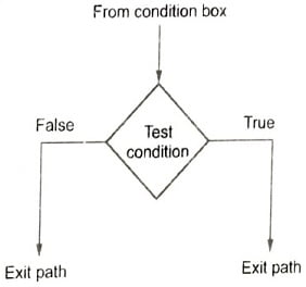
Decision Box
A decision box may be conditioned on a signal or a test of some kind. It represents the effect of input on control flow. The input condition is subjected to a test inside the diamond shape box. Two or more output represents exit paths dependent on the value of conditions in the decision box. For a binary bated condition, there are two paths. The figure shows the representation of the decision box.
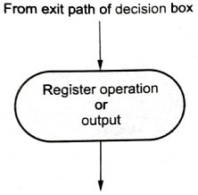
Condition Box
A conditional box is an output box that indicates outputs that are conditionally asserted. These outputs are called asynchronous or Mealy outputs. Inputs to this box come from one of the exit paths of decision boxes. Register operation or outputs are listed inside the box generated during the given state. The figure shows the representation of the conditional box.

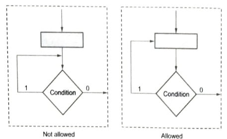
Rules for Drawing ASM Chart
- The entrance paths to an ASM block lead to only one state box.
- For a valid possible input condition there can be only one valid next state.
- Internal feedback to state box is not allowed.
Event Tables for Algorithmic State Machine
Timing diagrams shows time relationships and delays among various waveforms. In synchronous sequential circuits, the registers are updated at rising edge of the system clock. The clock period is decided by circuit parameters.
To summarize the resultant behavior of sequential logic event table is used. Certain symbols which are used in event table are listed below.
- X refers to input to the system.
- T refers to the system clock period.
- nT refers n times system clock period.
- ‘+’ refers to a moment after a given time.
- ‘-‘ refers to a moment before a given time.
- Z refers to output.
The event table consists of following fields – Time, Reset, X, State and Z.
Realization of ASM Charts
- The first step is to make a suitable state assignment for each state.
- Search all the states for which output Q is one.
- For each of these states find all of the links that lead into the state.
- The expression for the next state of Q is formed by ORing together all the terms found in, step 3.
- Similarly, the expression for output can be read directly from the ASM chart.
- Find the simplified expression for output and next-state equations with k-map using unused state assignment as a don’t care condition.
- Realize the ASM chart using gates and flip-flops.
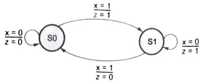
Finite State Machines
Definition: A model of computation consisting of a set of states, a start state, an input alphabet, and a transition function that maps input symbols and current states to a next state. Computation begins in the start state with an input string. It changes to new states depending on the transition function. There are many variants, for instance, machines having actions (outputs) associated with transitions (Mealy machine) or states (Moore machine), multiple start states, transitions conditioned on no input symbol (a null), or more than one transition for a given symbol and state (nondeterministic finite state machine), one or more states designated as accepting states (recognizer), etc. The finite state machine is also known as finite-state automation.
A state stores information about the past, i.e. it reflects the input changes from the system start to be the present moment. A transition indicates a state change and is described by a condition that would need to be fulfilled to enable the transition.
All action is a description of an activity that is to be performed at a given movement. There are several action types.
Entry action: Execute the action when entering the slate.
Exit action: Execute the action when exiting the state.
Input action: Execute the action dependent on present state and input conditions.
Transition action: Execute the action when performing a certain transition.
FSM can be represented using a state diagram (or state transition diagram). Besides this, several state transition table types are used. The most common representation is shown below: The combination of current state (B) and condition (Y) shows the next state (C). An FSM definition including the full actions information is possible using state tables.
| Current State / Condition | State A | State B | State C |
| Condition X | …… | …… | …… |
| Condition Y | …… | State C | …… |
| Condition Z | …… | …… | …… |
In addition to their use in modelling reactive systems, finite state automata are significant in many different areas, including linguistics, computer science, philosophy, biology, mathematics and logic.
In computer science, finite state machines are widely used in modelling of application behaviour, design of hardware digital systems, software engineering, compilers, and the study of computation and languages.